Introduction
Door Locks are critical to the security of the home and thus communication must be reliable and fast. This document brings together the many issues unique to door locks and guides the developer toward the most robust and interoperable implementation. These are mostly recommendations, not requirements and do not guarantee Z-Wave certification. Z-Wave allows for plenty of product differentiation, but it is important that common lock functions operate in the most interoperable fashion.
Z-Wave door locks entered the market in 2008. The problem was that at the time the Z-Wave Command Classes were missing standardized reporting of status of the lock and user codes. Initially Alarm CC was used by the locks to send various notifications to the hub to deliver status updates. The problem with this method is that each manufacturer used a unique set of commands to deliver the different status updates. Shortly after these initial locks hit the market and with the arrival of the Z-Wave Alliance, the Z-Wave specifications were updated and now locks can send standardized messages to deliver status changes. The standardized messages make Hub software much easier as basic operations can be received without the need for specialized code for each lock manufacturer.
Z-Wave Command Classes for Door Locks
SDS14224 Z-Wave Plus v2 Device Type Specification section 4.5.1 (in Version 10) specifies the Mandatory and Recommended Command Classes (CC) for Lock Device Types. Some command classes have a minimum version required for certification. However, the developer is free to choose the command class version that meets the product needs. As command classes have matured, commands have been added which in turn adds complexity and more code space. Every command in a command class must be implemented by the lock based on the version supported. If you don’t want to support some commands in a later version, then only declare the earlier versions in the Version CC.
Mandatory Command Classes
- Door Lock CC (V4 or later)
- Battery (V1) – unless the lock is mains powered
- Basic CC – 00=UNLOCK, FF=LOCK (does not appear in NIF)
- Security S0 CC – for backwards compatibility to older gateways that don’t support S2
- S0 may change to recommended in the future but is mandatory in 2020
Common Mandatory CC for All Z-Wave Plus v2 Devices
- Association, version 2
- Association Group Information
- Device Reset Locally
- Firmware Update Meta Data, version 5
- Indicator, version 3
- Manufacturer Specific
- Multi-Channel Association, version 3
- Powerlevel
- Security 2
- Supervision – See discussion below – you SHOULD be using Supervision!
- Transport Service, version 2
- Version, version 2
- Z-Wave Plus Info, version 2
Most of these command classes are handled by the SDK and/or the Z-Wave Application Framework (ZAF). There are some customizations to many of these command classes, but the effort is minimal.
Recommended Command Classes
- User Code CC – If the lock has a keypad this CC is used to program/enable the codes
- Notification CC – Send various lock status messages to the Lifeline NodeID (Gateway/Hub)
- Time CC – See the section below on the time/clock command classes
- Clock CC
- Time Parameters CC
- Generic Schedule CC – Defines time/date ranges to enable/disable User Codes
- Schedule CC – Simpler but less flexible schedules using any Z-Wave command
- Authentication CC – use with RFID, NFC, Mag cards etc. and link ScheduleIDs with User Codes
Other Command Classes
- Door Lock Logging CC
- Door lock logging CC provides a means to retrieve an audit trail of operations
- Typical use: If the hub is offline, a log of all operations is recorded and can then be sent when the hub comes back online
- Barrier Operator CC – Typically used with motorized entry gates which are like locks
- Entry Control CC -Used with RFID or other means that have ASCII strings
- Relies on the Hub to authenticate the string and then send an unlock command
- Typically used for Keypads which do not control a lock
- Use Authentication CC for locks
- Configuration CC (V3) – configure specific features that are not supported by other CCs
- See the Door Lock Configuration SET command which should provide most of the needed configuration
- Configuration CC should only be used if really necessary as it is less interoperable
- Application Status – Can be used to reply back to the Hub that the lock is currently busy and cannot execute the command just received
- Use Supervision instead
- Protection CC – enables a Child Protection mode
- AntiTheft CC (v3) – Locks the device so if stolen it is a brick
- Multi-channel – Multichannel should not be necessary
- Multi-command – Can be used to return several commands in a single frame to reduce battery consumption however with the smaller payload size in S2 it is not recommended
- Obsolete Command Classes – do not use these
- Schedule Entry Lock CC – use Generic Schedule CC instead
- Alarm CC – Use Notification CC (V3 or later)
Security Levels
Security S2 has three security levels and S0 has one for a total of four different security levels:
- Security S2 Access Control – Strongest Security level only used with devices that provide access to secure areas – door locks
- Security S2 Authenticated – SmartStart requires a QR code/DSK – lights/thermostats/sensors
- Security S2 UnAuthenticated – used by a small number of early S2 devices – generally not recommended – Does not require QR Code/DSK
- Security S0 – Legacy security mode – slower, uses more battery power, less secure than S2
The Security S2 Unauthenticated and S2 Authenticated keys are NOT recommended due to potential security holes. S2 is rapidly becoming commonplace so it is expected that S0 will no longer be mandatory but will change to recommended. S0 is slower, uses more battery power and is less secure than S2 due to the network key being exchanged using a known encryption key. Security S2 uses Diffie-Hellman elliptic curves to exchange the keys, an out-of-band DSK is required to join the network and Nonces are pre-computed enabling a single frame compared to three for S0 (Nonce Get, Nonce Report, Encrypted frame). Locks are required to use the Security S2 Access Control level.
Recommended Security Levels:
- S2 Access Control
- S0 if supported or if legacy support is desired (mandatory in 2020)
Reporting State Changes
All Z-Wave Plus devices are required to send to the Lifeline NodeID (typically the Hub) when their state changes. The Z-Wave Application Framework True-State Engine (TSE) can be used to send state changes. The primary state changes in a lock are:
- Secured vs. Non-secured (locked vs. unlocked)
- Keypad entry of a code
- Battery level
Schedules
Currently most locks rely on the Hub to install/remove User Codes and to manage the times and dates when the codes are valid. Thus, the lock need not know the current date/time and does not need to store schedules and apply them to User Codes. This makes the lock firmware simple and keeps the complexity of schedules with the Hub and its significantly greater processing, storage and user interface capabilities. However, many rental property agencies prefer the battery powered lock to have the schedules built-in so that even if there is an extended power or internet failure, the proper User Codes are enabled/disabled at the proper times. Thus, there is a desire to have these schedules managed within the lock itself. Fortunately, Z-Wave already has the command classes in place to support them, but schedules are complicated.
Generic Schedule CC – Recommended
Generic Schedule CC can set Time Ranges and then Schedules which are comprised of one or more Time Ranges. A Time Range has Start and Stop Date/Time fields and each field can be enabled or ignored. For example, a Time Range can be every Monday from 1pm to 3pm (date and minute fields are ignored) or can include specific dates like 2022 May 24th from 11:23am to 4:57pm. This makes the Time Range very flexible and able to specify virtually any type of date/time combination.
A Schedule is a list of Time Ranges that are either Included or Excluded to build the schedule. Thus, a Time Range of M-F 8am-5pm could be included but then 1 Jan 2022 from 4pm to 5pm could be excluded. In this example, the Schedule includes the first Time Range and Excludes the second. Generic Schedule only creates the ScheduleIDs. It does not hold any commands or perform actions. Authentication CC is then used to link a Schedule to a User Code or other authentication method. There are up to 64K Schedule and Time Ranges though each device reports the number supported in the Generic Schedule Capabilities Report. Due to the memory required for schedules and time ranges most devices will typically only have perhaps a dozen or so of each.
Schedule CC
Schedule CC is different than Generic Schedule in that Z-Wave commands are used instead of ScheduleIDs/AuthenticationIDs/UserCodes. Schedule CC is usable for any Z-Wave command and not just those that use the Schedule IDs. Schedule CC is most often used with thermostats or other devices that change state automatically based on the time/date. While Schedule CC can be used to execute User Code Set commands to enable/disable User Codes on a schedule, it is less flexible than Generic Schedule CC. For simple weekly schedules this CC will work OK but trying to build more complex schedules quickly becomes cumbersome.
Schedule Entry Lock CC
The Schedule Entry Lock CC has been deprecated and thus should not be used in new locks. Use the Generic Schedule CC instead. There are less than a dozen certified locks with Schedule Entry Lock CC. Hubs may want to control this CC to support specific locks but it is not required.
Authentication CC
Authentication CC is used to connect a User Code to a Generic Schedule. Authentication CC can also be used in conjunction with RFID, NFC, mag stripes, BLE or other forms of user authentication. It is then used to enable/disable various access methods based on a schedule. Thus, Authentication is flexible but with that flexibility comes complexity.
Time CC vs. Clock CC vs. Time Parameters CC
If a lock supports schedules to enable/disable user codes, then it needs some way to determine the date and time. For example, the cleaners code only works on Tuesdays from 2 to 4pm. How is a lock supposed to get the current local time and date so it knows when to enable the cleaners code?
There are three different command classes for getting various parts of the time/date. Time Command Class is mandatory for all Gateways and is the most full featured method. Unfortunately, not all gateways support it yet, so most devices need to support one of the others for use with older hubs. Clock CC is defined in SDS13781 – Z-Wave Application CC but the other two are defined in SDS13782.
| Time CC | Clock CC | Time Parameters CC | |
| Second | V1(Local) | V1 (UTC) | |
| Minute | V1(Local) | V1 | V1 (UTC) |
| Hour | V1(Local) | V1 | V1 (UTC) |
| Day of Week | V1 | ||
| Day of Month | V1(Local) | V1 (UTC) | |
| Month | V1(Local) | V1 (UTC) | |
| Year | V1(Local) | V1 (UTC) | |
| Time Zone Offset Hour, Minute | V2 | ||
| DST Offset | V2 | ||
| DST Start Month, Day Hour | V2 | ||
| DST End Month, Day Hour | V2 |
Time CC – Recommended
Time command class is described in SDS13782 (Z-Wave Management Command Class Specification). Time CC is mandatory for all Z-Wave Plus Gateways and thus is the recommended method for a lock to set its clock to the current local date and time. Time CC Version 2 adds time zones and daylight savings time support if desired however V1 provides the necessary functionality in most cases.
The Z-Wave specification recommends having an association group to identify the time server node however the Gateway is expected to have an accurate time reference so using the Lifeline is acceptable.
The Time CC does NOT have a date/time SET command. Thus, the hub cannot set the date/time and instead should wait for the lock to GET it. The hub can send a Time/Date REPORT to the lock when a lock is included in a network. However, the lock must send a Time GET command within the first few minutes to accurately set its internal clock. The lock should then periodically send a Time GET to ensure the internal clock remains accurate to the local time. Only the lock knows the accuracy of its real-time clock. Thus, the lock will determine how often it needs to update its internal clock and send a Time GET when needed. The hub should not send Time Reports unless responding to a Time GET other than immediately after inclusion. Note that for certification purposes a door lock CONTROLs Time CC, it does not SUPPORT it. The Hub is required to SUPPORT Time CC.
Time Parameters CC – Optional
The Time Parameters command can SET/GET/REPORT the year, month, day, hour, minute & second of the UTC time. However, it does not set the time zone which must be done via the Time CC V2. Thus, Time Parameters CC relies on the hub to send the current UTC time but the lock can also send a GET and adjust its internal clock to match the one from the hub. However, this requires support on the hub software which is not mandatory so not all hubs will be able to provide the current date/time.
Clock CC – NOT Recommended
Clock command class is sent by a Hub and can set the local weekday and time. Thus, it only supports a 7-day schedule since it cannot set the date, just the day of the week. Typically, the Hub would send a Clock Set as part of inclusion in the network. Since the clock on the lock will drift, the lock must periodically send a Clock Get to the Hub and to maintain time accurately. This method is NOT recommended. However, on some old hubs this is the only method available.
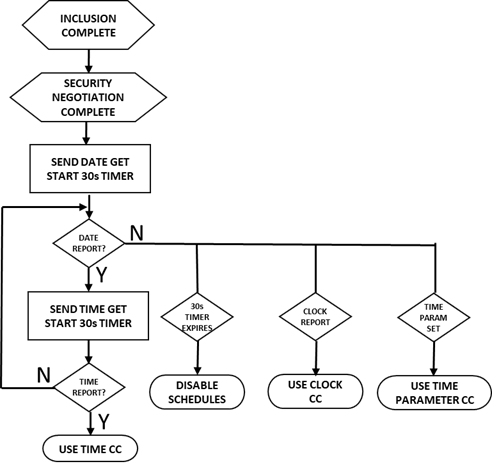
Recommended Time Setting Algorithm
The algorithm below provides a basic guide for setting the time. The first step is to wait for the inclusion and the security negotiation to complete. Then send a Time GET and start a 30 second timer. If a Time REPORT arrives before the end of the 30 second timer, then the Hub supports Time CC so use that. If the Hub instead sends either a Clock REPORT or a Time Parameters SET then that will set the initial time for the lock. The lock will have to continue to send periodic Clock GET commands to the Hub to maintain clock accuracy. If there is no response from the Hub, then the lock has no choice but to disable the schedule features as they require accurate local time.
Depending on the accuracy of the local clock circuitry, the functioning time setting command class should be used to update the local clock at a sufficient rate to match the desired settings. Typically, this would be once per day assuming a 100ppm or better 32Khz crystal is used for the clock (see section Real Time Clock (RTC) 32KHz Crystal below).
Notification CC
Notification CC was originally called Alarm CC which was deprecated at V2 and replaced with Notification CC. When the first Z-Wave locks were developed there was no standardized method for informing the Hub when a lock state changed. Each lock manufacturer was free to choose an Alarm Type and Alarm Level to communicate various status changes. Unfortunately, this resulted in non-standard and non-interoperable Z-Wave commands. Notification CC V3 defined a set of Access Control notification types and events which are described in SDS13713 which is a spreadsheet listing all standard notification types/events. For new lock developments it is recommended to use the standardized commands described here instead of the old Alarm CC ones (V8 or later is recommended). The Alarm CC can still be sent if the lock is joined using Security S0 for backwards compatibility, but their use is not recommended if the lock is joined using Security S2. Alternatively, a Configuration Parameter could be used to enable/disable the Alarm CC commands. Sending these old commands wastes battery power and clogs up the Z-Wave network.
Notification CC is typically used to communicate specific state changes beyond Door Lock or User Code CCs. There is overlap between some notifications and some Door Lock commands. The recommendation is to use Door Lock CC and only use Notification for cases that don’t have overlap. A few examples are shown in the Sample Communication section below.
Supervision CC
Supervision CC is mandatory for all S2 devices. Since locks provide property security and users have very high expectations for reliability and robustness of lock operation, it is strongly recommended that all communication to/from a lock be wrapped in Supervision CC. Supervision eliminates the need to send a Notification that a user code has been SET as the Supervision Report confirms that the command was received, decrypted and executed. See Appendix A for a sample implementation of Supervision CC for the door lock firmware.
The example below shows a lock being unlocked manually by the user. The lock needs to be 100% certain it informs the Hub that the door is now unlocked. To do that, the DoorLock_Operation Report is encapsulated with a Supervision GET command. The first attempt is blocked by RF noise but the protocol will automatically retry sending the frame up to five different routes using the mesh network because the ACK was not received. The second try delivers a frame to the Hub but due to more RF noise, the Hub is unable to decrypt the message. The Hub has already ACKed the frame so the protocol has retired the frame from the transmit queue and will not try again. However, the SDK has started a 500ms timer expecting a Supervision Report within that time. Since the Hub could not decrypt the message, it has discarded the frame. Once the 500ms timeout has expired, the lock will resend the frame. This time it gets thru and the Hub is able to decrypt the message and replies with a Supervision REPORT with a status of Success. At that point, the lock is 100% certain the frame has been delivered, decrypted and executed. The use of Supervision command class ensures delivery and execution of any Z-Wave command and should be used with any critical function of any device.

Door Lock Command Class
Most of Door Lock CC is straightforward and documented in SDS13781. The Lock Timeout vs. Auto-Relock function however needs a little extra explanation. The Door Lock Operation Set (V1) command includes the Mode which assigns either Timeout mode or Constant mode. The Door Lock Configuration Set (V1) command sets the timeout in Minutes + Seconds and whether the lock is by default in Constant or Timeout mode. Later versions of Door Lock CC enable sending a Timeout or an Auto-Relock time in the Operation Set command. Auto-Relock is in force ONLY if the lock is in Constant mode. If the lock is in Timeout mode then the normal Timeout Minutes/Seconds is used and the Auto-Relock values are ignored. Given the more common support of the Timeout Mode, it is recommended to use this mode for improved interoperability. Note that some locks have the timeout or mode as a configuration parameter. While it is acceptable to have these modes read/writeable via Configuration CC, the same values must also be reflected in the Door Lock Configuration commands.
Sample Communication
This section describes the communication between a lock and a hub in various scenarios. All communication is Security S2 encrypted which is shown in most of the examples. The recommendation is to encapsulate all frames in Supervision to ensure the frames was delivered and decrypted.
User Manually Locks/Unlocks
When the user manually locks or unlocks the lock by turning the bolt/lever, the lock must send to the Lifeline NodeID(s) (the Hub) the following:
| Byte # | Value | Name | Description |
| 1 | 0x6C | CmdClass | Supervision CC |
| 2 | 0x01 | Cmd | Supervision GET |
| 3 | Properties1 | Supervision SessionID incremented with each new GET | |
| 4 | 0x09 | Len | Supervision Length |
| 5 | 0x62 | CmdClass | Door Lock Operation CC V4 |
| 6 | 0x03 | Cmd | Door Lock Operation Report |
| 7 | LockMode | 00=unsecured, FF=secured – See SDS13781 table 44 | |
| 8 | Properties1 | In/out Handles Mode – table 45 | |
| 9 | DoorCondition | Door/bolt/latch state – table 46 | |
| 10 | 0xFE | TimeoutMin | Lock returns to secured after these many minutes |
| 11 | 0xFE | TimeoutSec | Lock returns to secured after these many seconds |
| 12 | TargetMode | Target Mode if in transition or LockMode | |
| 13 | 0x00 | Duration | Seconds to reach target mode – 0=already at target |
Note that Supervision CC is used to ensure the Hub has received and decrypted the frame.
A Notification CC can be sent if the lock was included using Security S0 for backwards compatibility. It is not recommended if the lock is using Security S2 which relies on the Supervision CC to ensure delivery.
| Byte # | Value | Name | Description |
| 1 | 0x71 | CmdClass | Notification CC |
| 2 | 0x05 | Cmd | Notification REPORT |
| 3 | 0x00 | V1AlarmType | V1Alarm can be non-zero IF documented in the user manual |
| 4 | 0x00 | V1AlarmLevel | These are used for backwards compatibility |
| 5 | 0x00 | Reserved | |
| 6 | 0xFF | Status | 00=notifications are disabled, FF=enabled |
| 7 | 0x06 | Type | 06=Access Control |
| 8 | Event | 01=Manual Lock, 02=Manual Unlock | |
| 9 | 0x00 | Properties1 | Parameters Length |
User Enters a Good User Code
A User Code of “1234” has been set in a deadbolt lock with a keypad at UserID=03. The lock is locked and then the user enters 1234 to unlock the lock.
A Notification CC is sent informing the Hub which User Code was used.
| Byte # | Value | Name | Description |
| 1 | 0x6C | CmdClass | Supervision CC |
| 2 | 0x01 | Cmd | Supervision GET |
| 3 | 0x13 | Properties1 | Supervision SessionID incremented since this is a new frame |
| 4 | 0x09 | Len | Supervision Length |
| 5 | 0x71 | CmdClass | Notification CC |
| 6 | 0x05 | Cmd | Notification REPORT |
| 7 | 0x00 | V1AlarmType | V1Alarm can be non-zero IF documented in the user manual |
| 8 | 0x00 | V1AlarmLevel | These are used for backwards compatibility |
| 9 | 0x00 | Reserved | |
| 10 | 0xFF | Status | 00=notifications are disabled, FF=enabled |
| 11 | 0x06 | Type | 06=Access Control |
| 12 | 0x06 | Event | 05=keypad Lock, 06=keypad Unlock |
| 13 | 0x63 | Param | User Code CC |
| 14 | 0x03 | Param | User Code CC cmd = REPORT |
| 15 | 0x03 | Param | UserID=0x03 |
| 16 | 0x01 | Param | UserID Status = occupied & enabled |
| 17 | 0x31 | Param | User Code = ASCII “1” |
| 18 | 0x32 | Param | User Code = ASCII “2” |
| 19 | 0x33 | Param | User Code = ASCII “3” |
| 20 | 0x34 | Param | User Code = ASCII “4” |
Optionally a Door Lock Operation could be sent to inform the Hub that the door is now unlocked.
| Byte # | Value | Name | Description |
| 1 | 0x6C | CmdClass | Supervision CC |
| 2 | 0x01 | Cmd | Supervision GET |
| 3 | 0x12 | Properties1 | Supervision SessionID=0x12 |
| 4 | 0x09 | Len | Supervision Length |
| 5 | 0x62 | CmdClass | Door Lock Operation CC V4 |
| 6 | 0x03 | Cmd | Door Lock Operation Report |
| 7 | 0x00 | LockMode | 00=unsecured, FF=secured – See SDS13781 table 44 |
| 8 | 0x00 | Properties1 | In/out Handles Mode – table 45 |
| 9 | 0x00 | DoorCondition | Door/bolt/latch state – table 46 |
| 10 | 0xFE | TimeoutMin | Lock returns to secured after these many minutes |
| 11 | 0xFE | TimeoutSec | Lock returns to secured after these many seconds |
| 12 | 0x00 | TargetMode | Target Mode if in transition or LockMode |
| 13 | 0x00 | Duration | Seconds to reach target mode |
User Enters a Bad User Code
Currently nothing is sent when the user enters a bad code. There have been discussions that the lock should send the bad code so that the Hub could collect statistics on how many times a user has tried to enter a code and what the code was. This would require a new Notification Access Control Event. Let us know what you think of this idea or get involved with the Z-Wave Alliance Standards Development Organization and make a proposal.
Hub Sends Lock/Unlock Command
A hub sends a Lock or Unlock command. Most locks take a few seconds to slide a bolt and this sequence shows the use of a Supervision Report with a WORKING status followed by a SUCCESS.
| Byte # | Value | Name | Description |
| 1 | 0x6C | CmdClass | Supervision CC |
| 2 | 0x01 | Cmd | Supervision GET |
| 3 | 0x95 | Properties1 | Supervision SessionID=0x15 with Status Updates |
| 4 | 0x03 | Len | Supervision Length |
| 5 | 0x62 | CmdClass | Door Lock Operation CC V4 |
| 6 | 0x01 | Cmd | Door Lock Operation SET |
| 7 | 0xFF | LockMode | 00=unsecured, FF=secured |
The lock immediately responds with a Supervision WORKING report with the More Status Updates bit set indicating another report will come within the next 7 seconds. The WORKING status means the lock is busy moving the bolt and it will take a few seconds to know for sure if it is properly engaged. If the Status Updates bit was 0, then only this supervision report would be sent. If the lock (or more typically a gate) takes more than 10 seconds to reach the final state it is suggested to send a WORKING report every 5-10s. Each time the Duration field should be updated with the estimated time to completion.
| Byte # | Value | Name | Description |
| 1 | 0x6C | CmdClass | Supervision CC |
| 2 | 0x02 | Cmd | Supervision REPORT |
| 3 | 0x95 | Properties1 | Supervision SessionID=0x15 – More Status Updates set |
| 4 | 0x01 | Status | WORKING – Once the bolt has finished moving another report will be sent |
| 5 | 0x07 | Duration | Next report will be in 7 seconds or less. The duration should be a worst-case number to handle the case when the lock is jammed. |
When the lock has completed the operation, it sends another Supervision Report this time with the Status Updates bit cleared and a status of SUCCESS (if the Status Updates bit was set in the Supervision GET). This frame should be sent as soon as the lock has completed the operation.
| Byte # | Value | Name | Description |
| 1 | 0x6C | CmdClass | Supervision CC |
| 2 | 0x01 | Cmd | Supervision GET |
| 3 | 0x15 | Properties1 | Supervision SessionID=0x15 |
| 4 | 0xFF | Status | SUCCESS |
| 5 | 0 | Duration | Target mode completed |
At this point the Hub is assured the lock has completed the operation because Supervision CC confirms the command was executed. However, most Hubs want to receive a status update so either a Notification CC, Access Control and Event of 0x03 (lock) or 0x04 (unlock) could be sent. It is recommended to send a Door Lock Operation Report wrapped in a Supervision Get as shown here.
| Byte # | Value | Name | Description |
| 1 | 0x6C | CmdClass | Supervision CC |
| 2 | 0x01 | Cmd | Supervision GET |
| 3 | 0x0A | Properties1 | Supervision SessionID=0x0A |
| 4 | 0x09 | Len | Supervision Length |
| 5 | 0x62 | CmdClass | Door Lock Operation CC V4 |
| 6 | 0x03 | Cmd | Door Lock Operation REPORT |
| 7 | 0xFF | LockMode | 00=unsecured, FF=secured |
| 8 | 0x00 | HandlesMode | In/out Handles Mode |
| 9 | 0x00 | DoorCondition | Door/bolt/latch state |
| 10 | 0xFE | TimeoutMin | Lock returns to secured after these many minutes |
| 11 | 0xFE | TimeoutSec | Lock returns to secured after these many seconds |
| 12 | 0xFF | TargetMode | Target Mode if in transition or LockMode |
| 13 | 0x00 | Duration | Seconds to reach target mode |
Hub Sends User Code Set
Supervision encapsulated User Code SET enabling the User Code of “1234” for User ID 5.
| Byte # | Value | Name | Description |
| 1 | 0x6C | CmdClass | Supervision CC |
| 2 | 0x01 | Cmd | Supervision GET |
| 3 | 0x01 | Properties1 | Supervision SessionID=0x01 |
| 4 | 0x08 | Len | Supervision Length |
| 5 | 0x63 | CmdClass | User Code CC |
| 6 | 0x01 | Cmd | User Code SET |
| 7 | 0x05 | UserID | User Identifier = 0x0005 |
| 8 | 0x01 | UserIDStatus | 0x00=available, 0x01=Access Enabled, 0x02=Disabled, 0x03=Messaging, 0x04=Passage Mode |
| 9 | 0x31 | UserCode1 | ASCII ‘1’ |
| 10 | 0x32 | UserCode2 | ASCII ‘2’ |
| 11 | 0x33 | UserCode3 | ASCII ‘3’ |
| 12 | 0x34 | UserCode4 | ASCII ‘4’ – total length of the code is 4 to 10 digits |
The lock would then send the Supervision CC REPORT with a value of SUCCESS if the User Code was properly executed otherwise it would return FAIL. If the UserID is more than 255, the Extended User Code Set command would be used. This command can also set multiple codes in a single frame.
When a Hub sends a User Code SET, the Hub typically wants confirmation that the code was in fact properly set. While this isn’t necessary if Supervision is used, it is good practice as that is the only method that a pre-S2 lock can confirm that the User Code was set. Since the Supervision Report already confirmed the User Code has been set, it is not necessary to wrap this frame in Supervision as it is merely informational. If the lock is using Security S0, the notification report confirming the User Code is recommended.
| Byte # | Value | Name | Description |
| 1 | 0x71 | CmdClass | Notification CC |
| 2 | 0x05 | Cmd | Notification REPORT |
| 3 | 0x00 | V1AlarmType | V1Alarm can be non-zero IF documented in the user manual |
| 4 | 0x00 | V1AlarmLevel | These are used for backwards compatibility |
| 5 | 0x00 | Reserved | |
| 6 | 0xFF | Status | 00=notifications are disabled, FF=enabled |
| 7 | 0x06 | Type | 06=Access Control |
| 8 | 0x0E | Event | 0E=New User Code added |
| 9 | 0x00 | Properties1 | Parameters Length = none |
Hub Sends a Duplicate User Code
If a Hub sends another User Code SET with a different UserID but with the same UserCode, the lock must return a Notification CC Type=Access Control (0x06) with an Event=New User Code Not Added (0x0F). This Notification should be sent encapsulated in Supervision CC if the lock is using S2.
Lock Sends Low Battery Warning
Most locks use simple alkaline batteries so version 1 of the battery command class is sufficient. Use the later versions for rechargeable or complex battery situations.
Battery powered locks should automatically send the Hub the battery level whenever the battery level changes by a significant amount. The lock should send an update if the battery level has changed by more than about 5% from the last report. The amount of change required to trigger an update is up to you, but it should be large enough to only send a battery update every several days or even weeks. Note that changes in temperature can cause the battery level to rise so the trigger should require the level to be lower. Be aware that most Hubs will occasionally poll the battery level which is why sending an update is not needed unless the level has changed significantly from the last report. Zero percent battery level should still allow the lock to operate reliably, but just barely. One Hundred percent battery level should be achievable with a wide range of batteries.
When the Critical Battery Level has been reached the lock must send a Low Battery warning (0xFF). Each lock will have a different Critical Level but it is typically in the 5% to 20% range. When the Critical level is reached for the first time, a low battery warning must be sent to the Lifeline. This warning must ONLY be sent once. Typically, a RAM variable holds a flag that is set when the low battery warning is sent and is only cleared upon power-on reset when the batteries are replaced. The Low Battery warning should be sent wrapped in Supervision command class to ensure the Hub received it. Normal battery reports do not need to be wrapped in Supervision.
Battery Report – Low Battery Warning
| Byte # | Value | Name | Description |
| 1 | 0x6C | CmdClass | Supervision CC |
| 2 | 0x01 | Cmd | Supervision GET |
| 3 | 0x01 | Properties1 | Supervision SessionID=0x01 |
| 4 | 0x03 | Len | Supervision Length |
| 5 | 0x63 | CmdClass | Battery CC |
| 6 | 0x03 | Cmd | Battery Report |
| 7 | 0xFF | Level | 0xFF=Low Battery Warning, 0-100 otherwise |
Lock Updates Local Time
If a lock has schedules that enable User Codes at certain days/times, it needs to know the current local time. See the discussion above about the different command classes that can be used and the hardware considerations later in this document for the necessary hardware to support time keeping. Typically, a lock will send this frame once per day to sync to the local time. Note that in this case Supervision is not used as the clock update is not important enough to warrant the extra overhead and battery power. The frame below should be sent within the first five minutes after inclusion if the Hub does not automatically set the time. Note that the time can be off by a few seconds due to system wide delays.
Lock sends the Hub a Time GET
| Byte # | Value | Name | Description |
| 1 | 0x8A | CmdClass | Time CC |
| 2 | 0x01 | Cmd | Time GET |
The Hub responds with Time REPORT that sets the local time to be 5:6:7 (6 minutes and 7 seconds after 5am)
| Byte # | Value | Name | Description |
| 1 | 0x8A | CmdClass | Time CC |
| 2 | 0x02 | Cmd | Time Report |
| 3 | 0x05 | Hour | Local Hour |
| 4 | 0x06 | Minute | Local Minute |
| 5 | 0x07 | Second | Local Second |
Lock sends the Hub a Date GET
| Byte # | Value | Name | Description |
| 1 | 0x8A | CmdClass | Time CC |
| 2 | 0x03 | Cmd | Date GET |
The Hub responds with Date REPORT that sets the local date to be 10 September 2019
| Byte # | Value | Name | Description |
| 1 | 0x8A | CmdClass | Time CC |
| 2 | 0x04 | Cmd | Date Report |
| 3 | 0x07 | Year1 | Local year MSB |
| 4 | 0xE3 | Year2 | Local year LSB – 0x7E3=2019 |
| 5 | 0x09 | Month | Local Month – 0x09=September |
| 6 | 0x0A | Day | Local Day – 0x0A=10th day |
The lock must calculate the day of the week based on the current date. The Time Offset Get command in V2 could also be used to get the daylight savings date/time if desired. Checking the local time/date at around 3:10am each day should keep the lock accurate to the current local daylight savings time.
Generic Schedule to Enable a User Code
The following sequence assigns User Code 0x05 to be enabled M-F 8am-5pm except on 5 June 2019 from 1:23pm to 6:45pm. First step is to SET two Time Ranges (01 and 02). The Hub should first send a Generic Schedule Capabilities Get to determine how many Time Ranges and Schedules the lock supports.
Time Range Monday thru Friday 8am to 5pm
| Byte # | Value | Name | Description |
| 1 | 0x6C | CmdClass | Supervision CC |
| 2 | 0x01 | Cmd | Supervision GET |
| 3 | 0x09 | Properties1 | Supervision SessionID=0x09 |
| 4 | 0x15 | Len | Supervision Length |
| 5 | 0xA3 | CmdClass | Generic Schedule |
| 6 | 0x03 | Cmd | Generic Schedule Time Range Set |
| 7 | 0x00 | TRngID1 | |
| 8 | 0x01 | TRngID2 | Time Range ID=0x0001 |
| 9 | 0xBE | Weekday | Weekday Mask = M-F |
| 10 | 0x00 | StartYear1 | Note the InUse bit (MSB) is zero for all fields that are not used |
| 11 | 0x00 | StartYear2 | Start Year not used |
| 12 | 0x00 | StopYear1 | |
| 13 | 0x00 | StopYear2 | Stop Year not used |
| 14 | 0x00 | StartMon | Start Month |
| 15 | 0x00 | StopMon | Stop Month |
| 16 | 0x00 | StartDay | Start Day |
| 17 | 0x00 | StopDay | Stop Day |
| 18 | 0x00 | StartHour | Start Hour |
| 19 | 0x00 | StopHour | Stop Hour |
| 18 | 0x00 | StartMin | Start Minute |
| 19 | 0x00 | StopMin | Stop Minute |
| 20 | 0x88 | DayStartHr | Daily Start Hour = 8am |
| 21 | 0x91 | DayStopHr | Daily Stop Hour = 17:00=5pm |
| 22 | 0x00 | DayStartMin | Daily Start Minute |
| 23 | 0x00 | DayStopMin | Daily Stop Minute |
Time Range 5 June 2019 from 1:23pm to 6:45pm:
| Byte # | Value | Name | Description |
| 1 | 0x6C | CmdClass | Supervision CC |
| 2 | 0x01 | Cmd | Supervision GET |
| 3 | 0x0A | Properties1 | Supervision SessionID=0x0A |
| 4 | 0x15 | Len | Supervision Length |
| 5 | 0xA3 | CmdClass | Generic Schedule |
| 6 | 0x03 | Cmd | Generic Schedule Time Range Set |
| 7 | 0x00 | TRngID1 | |
| 8 | 0x02 | TRngID2 | Time Range ID=0x0002 |
| 9 | 0x00 | Weekday | Weekday Mask not used |
| 10 | 0x87 | StartYear1 | |
| 11 | 0xE3 | StartYear2 | Start Year = 2019 |
| 12 | 0x87 | StopYear1 | |
| 13 | 0xE3 | StopYear2 | Stop Year = 2019 |
| 14 | 0x86 | StartMon | Start Month = June |
| 15 | 0x86 | StopMon | Stop Month = June |
| 16 | 0x85 | StartDay | Start Day = 5th |
| 17 | 0x85 | StopDay | Stop Day = 5th |
| 18 | 0x8E | StartHour | Start Hour = 1pm |
| 19 | 0x92 | StopHour | Stop Hour = 6pm |
| 20 | 0x97 | StartMin | Start Minute = 23 minutes after the hour |
| 21 | 0xAD | StopMin | Stop Minute = 45 min after the hour |
| 22 | 0x00 | DayStartHr | Daily Start Hour |
| 23 | 0x00 | DayStopHr | Daily Stop Hour |
| 24 | 0x00 | DayStartMin | Daily Start Minute |
| 25 | 0x00 | DayStopMin | Daily Stop Minute |
Now that the two Time Ranges have been defined, the next step is to link them to each other to create a ScheduleID. In this case Time Range 0001 is being INCLUDED and Time Range 0002 is being EXCLUDED to make the desired schedule.
| Byte # | Value | Name | Description |
| 1 | 0x6C | CmdClass | Supervision CC |
| 2 | 0x01 | Cmd | Supervision GET |
| 3 | 0x0B | Properties1 | Supervision SessionID=0x0B |
| 4 | 0x09 | Len | Supervision Length |
| 5 | 0xA3 | CmdClass | Generic Schedule |
| 6 | 0x06 | Cmd | Generic Schedule Schedule Set |
| 7 | 0x00 | SchedID1 | |
| 8 | 0x01 | SchedID2 | Schedule ID = 0001 |
| 9 | 0x02 | NumIDs | Number of Time Range IDs = 2 |
| 10 | 0x80 | TimeRngID1 | |
| 11 | 0x01 | TimeRngID2 | Include Time Range 0001 |
| 12 | 0x00 | TimeRngID1 | |
| 13 | 0x02 | TimeRngID2 | Exclude Time Range 0002 |
Finally, the Authentication CC is used to link the Schedule ID to the User Code CC UserID
| Byte # | Value | Name | Description |
| 1 | 0x6C | CmdClass | Supervision CC |
| 2 | 0x01 | Cmd | Supervision GET |
| 3 | 0x0C | Properties1 | Supervision SessionID=0x0C |
| 4 | 0x0A | Len | Supervision Length |
| 5 | 0xA1 | CmdClass | Authentication CC |
| 6 | 0x06 | Cmd | Authentication Technologies Combination Set |
| 7 | 0x00 | AuthID1 | |
| 8 | 0x05 | AuthID2 | Schedule ID = 0005 – can be any value but matching with the UserID is easier to match them up |
| 9 | 0x01 | FallBack | Fallback Status = 01 = enable access based on the schedule |
| 10 | 0x00 | UserID1 | |
| 11 | 0x05 | UserID2 | User Code CC UserID=0005 |
| 12 | 0x00 | SchedID1 | |
| 13 | 0x01 | SchedID2 | Generic Schedule CC ScheduleID=0001 |
| 14 | 0x00 | NumAuthID | Only the User Code is enabled |
In all cases Supervision should be used to confirm the schedule and time ranges are set properly. Alternatively, a GET should be used if the lock is only using security S0. If NFC, BLE or some other authentication technology is used then the NumAuthID would be more than zero to include these other forms of authentication.
Lock Has a Hardware Failure
If a lock has some sort of a hardware failure, there are several Notification Events that can be sent. The most common is the lock is jammed where the bolt is neither in the locked or unlocked position but somewhere in between. Other options are to send a Home Security – Tamper event when the battery cover is removed. The Impact Detected event could be used if an accelerometer detects the lock being smashed. If someone is jamming the RF in an attempt to bypass the lock, then an RF Jamming message could be sent. In this case the lock should store the RF jamming message if the message is not acknowledged by the Hub due to the jamming. The lock should continue to attempt delivery at ever larger timeouts between retries.
| Byte # | Value | Name | Description |
| 1 | 0x6C | CmdClass | Supervision CC |
| 2 | 0x01 | Cmd | Supervision GET |
| 3 | 0x01 | Properties1 | Supervision SessionID=0x01 |
| 4 | 0x08 | Len | Supervision Length |
| 5 | 0x71 | CmdClass | Notification CC |
| 6 | 0x05 | Cmd | Notification Report |
| 7 | 0x00 | V1AlarmType | V1Alarm can be non-zero IF documented in the user manual |
| 8 | 0x00 | V1AlarmLevel | These are used for backwards compatibility |
| 9 | 0x00 | Reserved | |
| 10 | 0xFF | Status | 00=notifications are disabled, FF=enabled |
| 11 | 0x06 | Type | 06=Access Control |
| 12 | 0x0B | Event | 0B=Lock Jammed |
The lock should also send a Door Lock Operation Report with a value of 0xFE (Door Mode Unknown) if the bolt is not in either the Locked or Unlocked mode.
Z-Wave Long Range

Z-Wave Long Range (ZWLR) support is recommended for locks. Z-Wave Long Range is a star topology with very long range. ZWLR is ideal for a battery backed up hub to talk directly to a distant lock even if the power is out and the Z-Wave mesh repeaters are offline. ZWLR will be available at the end of 2020 and is a software upgrade that can be OTAed to existing units. RF regulatory testing (FCC) may need to be redone to ensure ZWLR meets the applicable regulatory limits.
Hardware Considerations
The 700 series Z-Wave hardware is typically a FLiRS (Frequently Listening Routing Slave) device. Typical power consumption in this mode is on the order of 10uA average with brief peaks of 12mA during a transmit. Once every second the chip briefly wakes up and listens for a Wakeup Beam from the hub or an adjacent node. If the hub wants to talk to the lock it sends the Beam which wakes up the lock and then the two can communicate. Once the communication is complete the lock will again enter a low-power state. The 250ms FLiRS mode can be used to reduce the latency of waking the lock with a tradeoff of additional power draw.
Real Time Clock (RTC) 32KHz Crystal
Most locks need to accurately measure time and keep schedules of when to enable User Codes. The 700 series has an internal low power Low Frequency RC Oscillator (LFRCO=32KHz). However, the oscillator is not accurate enough to keep the schedule accurate without frequent updates from the Time Server (LFRCO can drift by more than 1min/hour). Thus, it is recommended to use a 32KHz crystal connected to the LFXO of the EFR32. A low cost 100ppm 32KHz crystal can provide accuracy of 9s per day. Note that if your lock does not support Time CC then an external crystal is not needed.
- Use a 32KHz crystal for the LFXO if schedules are supported
One MCU or Multiple?
The Z-Wave 700 series is an ARM processor with built-in cryptography accelerators and plenty of low power peripherals. The ZGM130S has plenty of GPIOs and can be easily extended using simple GPIO expanders via I2C or SPI. In most cases the ZGM130S is more than powerful enough to run the entire lock using the single processor. This avoids the complexity and security issues involved with using multiple microcontrollers within the lock. If a multi-MCU solution is chosen, the communication method between the ZGM130 and the lock MCU should be a UART, SPI or I2C and should be encrypted. Do NOT use the SerialAPI on the ZGM130! The SerialAPI is intended for use with Internet Gateway processors with large amounts of FLASH/RAM/CPU. The SerialAPI does NOT provide support for security encryption/decryption which is built-in to the embedded SDK. The recommendation is to develop your own encrypted serial protocol between processors.
Appendix A: Supervision Encapsulation End Device Example
Z-Wave SDK 7.14 does not have direct support for encapsulating frames with Supervision CC. However, it is easy to add manually. The example below simply wraps the DoorLockOperationReport with the SuperVisionGet IF the device was added as S2 which means the Hub support Supervision CC. The frame is not encapsulated if responding to a GET from the Hub.
In CC_DoorLock.c - Add the following code to this function:

 static uint8_t prepare_operation_report(ZW_APPLICATION_TX_BUFFER *pTxBuffer, uint8_t enableSuper)
 {
   ZW_APPLICATION_TX_BUFFER * ptr = pTxBuffer;
   memset((uint8_t*)pTxBuffer, 0, sizeof(ZW_APPLICATION_TX_BUFFER) );
   uint8_t len=sizeof(ZW_DOOR_LOCK_OPERATION_REPORT_V4_FRAME);

   if (SECURITY_KEY_S2_ACCESS == GetHighestSecureLevel(ZAF_GetSecurityKeys()) && enableSuper) { // add supervision if S2 enabled
     ptr->ZW_SupervisionGetFrame.cmdClass = COMMAND_CLASS_SUPERVISION;
     ptr->ZW_SupervisionGetFrame.cmd = SUPERVISION_GET;
     DL_SessionID = CC_SUPERVISION_ADD_SESSION_ID((DL_SessionID+1));
     ptr->ZW_SupervisionGetFrame.properties1 = DL_SessionID;
     ptr->ZW_SupervisionGetFrame.encapsulatedCommandLength = sizeof(ZW_DOOR_LOCK_OPERATION_REPORT_V4_FRAME);
     ptr=(ZW_APPLICATION_TX_BUFFER*)((uint8_t*)ptr+sizeof(ZW_SUPERVISION_GET_FRAME)); // skip 4 bytes
     len+=sizeof(ZW_SUPERVISION_GET_FRAME);
   }
   ptr->ZW_DoorLockOperationReportV4Frame.cmdClass = COMMAND_CLASS_DOOR_LOCK_V4;
   ptr->ZW_DoorLockOperationReportV4Frame.cmd = DOOR_LOCK_OPERATION_REPORT_V4;
   cc_door_lock_operation_report_t operation_report;
   CC_DoorLock_OperationGet_handler(&operation_report);
   ptr->ZW_DoorLockOperationReportV4Frame.currentDoorLockMode = (uint8_t)operation_report.mode;
   ptr->ZW_DoorLockOperationReportV4Frame.properties1 =
       (operation_report.outsideDoorHandleMode << 4) | operation_report.insideDoorHandleMode;
   ptr->ZW_DoorLockOperationReportV4Frame.doorCondition = operation_report.condition;
   ptr->ZW_DoorLockOperationReportV4Frame.lockTimeoutMinutes = operation_report.lockTimeoutMin;
   ptr->ZW_DoorLockOperationReportV4Frame.lockTimeoutSeconds = operation_report.lockTimeoutSec;
   ptr->ZW_DoorLockOperationReportV4Frame.targetDoorLockMode = operation_report.targetMode;
   ptr->ZW_DoorLockOperationReportV4Frame.duration = operation_report.duration;
   return(len);
} 