Detecting RF Jamming

Cheap RF Transmitter

All wireless protocols can be jammed often using an inexpensive battery powered transmitter. The protocol doesn’t even have to be radio frequency (RF) based as Infra-Red (IR) and any other communication medium that travels thru the air can be jammed by blasting out noise in the same spectrum as the protocol. Think of a busy street corner where you and a friend are having a conversation and a firetruck with their sirens blareing go by. Your conversation stops because your friend simply can’t hear you above all the noise. The same thing can happen in Z-Wave where a “bad actor” brings a small battery powered transmitter and blasts out RF in the same frequency bands that Z-Wave uses. In this post I’ll explain how to jam Z-Wave and also how to detect and inform the user that jamming has occurred.

Security System Requirements

Jamming applies primarily to security systems. After all, if someone wants to jam your house from turning on the kitchen lights at night, what’s the point other than to get a laugh when you bang your knee into the table? Z-Wave has enjoyed a great deal of success in the security system market. Z-Wave is interoperable, easy to use, low-power and the mesh networking protocol means users or installers don’t have to be concerned with getting everything to talk to everything else as the protocol automatically handles (mostly) everything. Security systems however are very concerned about jamming to the point that Underwriters Laboratory has a specification for it. UL1023 is the US standard for Safety Household Burglar-Alarm Systems.

The reality of the situation for a security system is that it is unlikely a burglar will try to bypass your security system by jamming it. Burglars are simply not that tech savvy. The FBI doesn’t even track the numbers of burglaries via jamming – one would assume because the number is essentially zero. A burglar will simply bash in a window or door or more often simply walk in an unlocked door. However, if it’s easy enough and cheap enough, a burglar might just try! CNET demonstrated just how easy it is to use a $3 transmitter to bypass a popular security system using a cheap RF transmitter. Regardless of the reality of the situation, the bad press of having an easy to jam security system can crater a company.

Anti-Jamming Techniques in Z-Wave

Z-Wave was designed from day one to be robust and reliable. The very first requirement for robustness is to acknowledge that the device receiving the message did in fact receive it. Every Z-Wave message is acknowledged (ACK) otherwise the sender will try again using different mesh routes or other RF frequencies. After several retries, the protocol will give up and the application can then decide if it wants to try even more ways to deliver the message. If the message is not very important (like a battery level report), the application can just drop it. If a sensor detects smoke! Then the application will continue trying to get this life-safety message thru in every way possible for as long as possible.

Z-Wave requires two-way communication – all messages are acknowledged

Here’s a list of the techniques Z-Wave uses for robustly delivering messages:

  • Z-Wave
    • All frames are Acknowledged
    • Multiple mesh routes
    • Frequency Hopping – Two frequencies – 3 different baud rates (in US)
    • RSSI Measurements indicating jamming
    • Supervision CC confirms decryption & data integrity
  • Z-Wave Long Range
    • All frames are Acknowledged
    • Dynamic TX Power
    • Frequency hopping to alternate channel
    • RSSI Measurements indicating jamming
    • Supervision CC confirms decryption & data integrity

Even with all these different measures in place, it is still possible to jam Z-Wave. But it’s not cheap nor is it easy. But let’s give it a try for fun!

Jamming Z-Wave

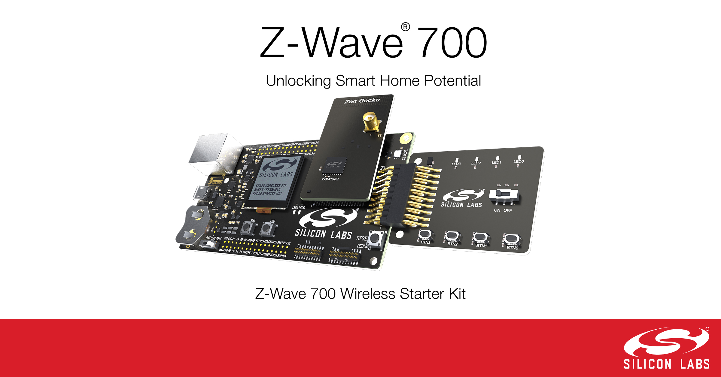
Jamming Z-Wave starts with a Silicon Labs Z-Wave Developers Kit and Simplicity Studio. However, these kits are not cheap costing at least $150 for just one. It may be possible to find a cheap 900MHz transmitter but you will need two of them and they must have the ability to tune them to the specific Z-Wave frequencies of 908.4MHz and 916MHz in the US. These are not going to be $3 battery powered transmitters and they require a significant amount of technical knowledge. Neither cheap nor easy so I think we’re pretty safe from your typical burglar.

Z-Wave uses two channels (frequencies) in the US: 908.4MH for 9.6 and 40Kbps and 916MHz for 100Kbps. Z-Wave Long Range (ZWLR) also has two channels but uses spread-spectrum encoding which spreads the signal out across a band of frequencies centered at 912MHz and 920MHz. By using two channels Z-Wave is frequency agile which makes it harder to jam since you need two transmitters instead of just one. The spectrum analyzer plot below shows four DevKits blasting all 4 channels at once.

Z-Wave jamming all four frequencies – 912 & 920 are Z-Wave Long Range

Creating the jammer firmware utilizes the RailTest utility in Simplicity Studio V5. Select the DevKit in the Debug Adapters window, click on the Example Projects & Demos tab then check the Proprietary button. The only example project should be the “Flex (RAIL) – RAILtest application”. Click on Create and use the defaults. The default frequency will state it is 868 but ignore that as the Z-Wave modes are all built into RailTest and do not need to be configured. Once the project is created, click on Build and then download to a devkit. Right click on the devkit in the Debug Adapters window and click on Launch Console. Click on the Serial 1 tab then click in the command box at the bottom and press ENTER. You should get a RailTest prompt of >.

Once you're at the RailTest prompt, enter the following commands:

rx 0                 -- disables the radio which must be done before changing the configuration
setzwavemode 1 3     -- Puts the radio into Z-Wave mode
setpower 24 raw      -- 24=0dbm radio transmit power - valid range is 1 to 155 but is non-linear
setchannel 0         -- ch0=916 ch1=908.4 ch2=908.42 - ZWLR ch0=912 ch1=920
setzwaveregion 1     -- EU=0, 1=US, 13=US Long Range
Do one of the following 2 commands:
SetTxTone 1          -- narrow band Carrier Wave - unmodulated
SetTxStream 1        -- Pseudo-Random data - modulated and in ZWLR uses Spread Spectrum (DSSS) 
Use the same command with a 0 to turn the radio off
Remember to "rx 0" before changing any other configuration values

RAILtest is a powerful utility and can do all sorts of things beyond just Z-Wave. The radio in the Silicon Labs chips are Software Defined Radios, they can be customized to many common frequency bands. It is easy to create customized versions of RAILtest that will transmit a carrier wave (CW) or a modulated signal at just about any frequency band, not just Z-Wave. But that’s more complex than I have time to discuss here.

Now that we know how to jam, how do we detect it and inform the user that jamming is taking place? Detecting jamming takes place at both ends of the Z-Wave network, the Controller and the End Device. Let’s first look into the End Device which in a security system is typically a motion sensor or a door/window sensor.

End Device Jamming Detection

Most end devices are battery powered so they spend most of their time sleeping and are completely unaware of any RF jamming that might be taking place. Only when motion is detected or a door is opened will the sensor wake up and find the radio waves being jammed. The best way to check for RF jamming is to first try to send a message. When the message fails to be acknowledged, then start looking to see if jamming is occurring.

The Z-Wave Application Framework (ZAF) handles sending the message and eventually calls a callback to report status. The callback comes through EventHandlerZwCommandStatus() which will be called several seconds after sending the message. The protocol tries various mesh routes, power levels and baud rates which takes time so be sure to stay awake long enough to receive the callback. The callback returns the TxStatus variable which is typically TRANSMIT_COMPLETE_OK (0x00) which means the message was delivered. But if jamming is taking place and the radio was unable to go through it, you’ll get a TRANSMIT_COMPLETE_FAIL (0x02). This status is different than the TRANSMIT_COMPLETE_NO_ACK (0x01) which means the message was not acknowledged which is usually because the destination is offline but could also be due to jamming.

The next step is to verify that jamming is taking place by getting the current Received Signal Strength Indicator (RSSI) level by queuing the EZWAVECOMMANDTYPE_GET_BACKGROUND_RSSI event . The RSSI is a simple value in dB of the strength of signal at the radio receiver when its not actively receiving a frame. In normal operation, this value should be around -100dB. Every environment is different so the threshold for the radio being jammed needs to be a value that is significantly higher than the average value. This is particularly tough in dense housing like apartments where perhaps every unit has a Z-Wave network. This results in a relatively high RSSI average. The key here is you can’t use a simple hard-coded threshold for jamming detection based on RSSI. Instead you must average the RSSI values across a long time-span (typically hours).

Z-Wave Notification of Jamming

The next step after detecting jamming has occurred is to notify the hub. But if the jamming is still in progress, how can the notification get thru? Naturally you can’t get thru while the jamming is still happening. The trick is to keep trying and hope that the jamming is short term. The problem is that a battery powered sensor can’t keep trying constantly as it will run out of battery power perhaps in just a few minutes. You must manage battery power and at the same time keep trying with a longer and longer timeout between attempts. At some point the jamming should end, perhaps hours after the initial break-in but the jammer will eventually run out of battery power.

The Z-Wave Notification Command Class has a pre-defined value for RF Jamming – Notification Type of Home Security (0x07) with an Event of RF Jamming (0x0C) and the current average RSSI level. This notification is a critical notification so it should be wrapped in Supervision Command Class to guarantee it has been delivered and understood by the controller.

Sample Code

The code below first checks the TxStatus, if is not OK, then the RSSI level is checked by queuing the GET_BACKGROUND_RSSI event. Once the RSSI is sampled, the function will be called again with the switch going thru the GET_BACKGROUND_RSSI case below. This section of code then compares the current RSSI level with a background RSSI level and if the current level is above it then the SendRFJamNotificationPending global variable is set. When a frame is able to get thru then the pending RF Jam notification is sent since it appears the jamming has ended. This ensures the Hub is informed that there was jamming so the Hub can then decide if it needs to inform the user. The basics of the algorithm are coded here:

... 
static void EventHandlerZwCommandStatus(void)
...
switch (Status.eStatusType)    
...
    case EZWAVECOMMANDSTATUS_TX:  // callback from attempted message delivery
...
            
        if (pTxStatus->TxStatus != TRANSMIT_COMPLETE_OK) { // failed to deliver - check RSSI
            EZwaveCommandType event = EZWAVECOMMANDTYPE_GET_BACKGROUND_RSSI;
            QueueNotifyingSendToBack(g_pAppHandles->pZwCommandQueue, &event, 0); // Queue GET_RSSI
        } else { // message delivered OK
            // more cleanup happens here...
            if (SendRfJamNotificationPending) { // Is there a pending Jam Notification?
               SendRfJamNotificationPending=false;   // Send it!
               void * pData = PrepareNotifyJamReport(&zaf_tse_local_actuation);
               ZAF_TSE_Trigger((void *)CC_NotifyJam_report_stx, pData, true);
            }
        }
...
    case EZWAVECOMMANDSTATUS_GET_BACKGROUND_RSSI:  // only called if failed to deliver a message
        if (Status.Content.GetBackgroundRssiStatus.rssi > BackgroundRSSIThreshold) {    
            // Set a global to send an RF Jamming Notification which will be sent when jamming ends
            SendRfJamNotificationPending=true;
            SendRfJamNotifRSSI= Status.Content.GetBackgroundRssiStatus.rssi;
        }
... // Not shown are application level retries and various other checking

Now that we have jamming detection enabled on the end-device side, let’s look at the controller end of the communication.

Controller Jamming Detection

Obviously the main thing the controller needs to do is react to a jamming notification from an End Device. The ultimate action the controller performs is left to the controller developer but clearly the end user should be notified that jamming has been detected. But that notification needs to be qualified with enough information about the average RSSI noise level to avoid false jamming detection notifications.

If the jammer is way out at 200+ meters, the RSSI level may not jump up significantly as measured by the controller. Thus, it is important to react to the End Device notification of jamming. However, the controller must poll the RSSI level at regular intervals to determine if jamming is taking place nearby. The question is how often should it poll and when to react to a sudden change in the RSSI level? There is no definite answer to this question other than “it depends” and it depends on a lot of different factors. Typically, the RSSI should be sampled a few times per minute – perhaps every 30 seconds. If a value seems unusually high, perhaps sample several more times at a much faster rate to confirm that the RSSI has jumped and its not glitch. Like the End Device case, the average RSSI value needs to be calculated across a fairly long time frame (minutes to perhaps an hour) and when there is a change from the average value then the user should be notified.

ZW_GetBackgroundRSSI

The SerialAPI function ZW_GetBackgroundRSSI() (0x3B) will return three or four bytes of RSSI values for the various channels supported by the controller. This function can be sent to the Z-Wave controller frequently as it does not cause any delays in the radio. It does use UART bandwidth so it can’t be called too frequently or it may interfere with normal Z-Wave traffic. The polling function should coded with a low priority so it is only sent when the UART has been idle for a few seconds to avoid collisions with Z-Wave radio traffic. The one-byte RSSI values are coded as shown in the table below.

RSSI values returned by the ZW_GetBackgroundRSSI():

HexDecimal (2s Comp)Description
0x80-0xFF-128 – -1Measured RSSI in dBm
0x00-0x7C0 – 124Measured RSSI in dBm
0x7D125RSSI is below sensitivity and cannot be measured
0x7E126Radio saturated and could not be measured as it is too high
0x7F127RSSI is not available

Typically a 700 series Z-Wave controller will measure about -100dBm when the airwaves are fairly quiet. During a transmission the RSSI is often about -30dBm when the node is within a few meters of the controller.

TxStatusReport

The TxStatusReport is returned after a frame was transmitted which includes several fields with a variety of RSSI measurements. There is a Noise Floor of the sender as well as a NoiseFloor of the receiver. The RSSI values can be monitored during normal Z-Wave traffic without polling. It is best to use these values while Z-Wave traffic is taking place and to temporarily pause the polling while the Z-Wave UART is busy. Once the UART is idle, resume RSSI polling.

Missing Heartbeats

Another aspect of jamming is that battery powered devices typically send a “heartbeat” message every hour so the controller knows for sure the device is online and working (mostly that the battery isn’t dead). The controller should be keeping track of how long it has been since the last time a battery powered node has checked in and if it has missed two or at most three heartbeats, the controller should inform the user (or the installer) that the device is offline and unable to communicate. If the battery was already low, then the battery is probably dead. If the battery was fine, then there is a possibility that the device is being jammed.

Jasco Motion Dimmer Explained

The Jasco Motion Dimmer is an ideal Z-Wave product for home automation. We want the lights to come on automatically when we enter a room and off again when everyone has left. The motion sensing needs to be reliable and sensitive and ideally not involve changing batteries every few months. Thus, a wall mounted, always-on dimmer with a built-in motion sensor fits our needs perfectly. In this blog article I’ll explain a few tricks to getting the most out of this handy device.

Configuration Parameters

The Jasco Motion Dimmer has 18 configuration parameters. The parameters can be set by reading the documentation and then programming them using complex combinations of button presses. But, with a Z-Wave device, it’s much easier to program them via Z-Wave. Most Hubs allow you to program the configuration parameters though the process to do so is different with every Hub. The parameters are briefly described on the Jasco web site ezzwave and on the Z-Wave Alliance web site. However, these brief descriptions don’t clearly describe what the parameter does and more importantly, what the best settings are to get the most out of this device.

Several parameters are two bytes instead of just one even though the value will typically fit in one (the value is 0-255). The parameters listed with a (2) in the Name field below means they are two bytes. If there is no (2) in the name then just send one byte. Sending just one byte to the 2 byte parameters can confuse the dimmer and it may not set the parameter to the desired value. The result is frustration as you sent it your desired value but it didn’t take it or set it to what appears to be some random value. Always send the proper number of bytes for each specific parameter. Some Hubs will handle this for you, but others must be done manually.

The table below is the list of all parameters with the less important ones greyed out and my own more detailed description of what each parameter does.

#NameDefaultDescription
1Timeout5Motion Sensor Timeout
0=5s test mode
1-254=minutes
255=disable
Time the lights remain on in Occupancy mode
2Assoc dim2550=99 dim level
255=last ON level
Dim level to send to associated lights. The Hub is better at controlling other lights so ignore this parameter.
3Mode31=Manual – Motion sensor does not control the local load
2=Vacancy – only turns lights off
3=Occupancy – Lights on when motion detected and off when none after Timeout
4Invert buttons00=normal (top=up, bottom=down)
1=invert (top=down, bottom=up)
If you accidentally install the dimmer upside down, inverting it will correct your mistake
6Motion Enable10=disable
1=enable
Why would you disable motion sensing?
7Steps via Z-Wave1Leave at 1
See the Ramp Rate discussion below
8Speed via Z-Wave (2)3Number of seconds for the dimmer to go from 0 to 100% via a Z-Wave command
9Steps via button1Leave at 1
10Speed via button (2)3Number of seconds for the dimmer to go from 0 to 100% via a button press or the motion sensor
11Steps via AllOnOff1AllOnOff commands are obsolete
12Speed via AllOnOff (2)3Leave at default
13Motion Sensitivity21=high – detects people at a distance
2=Medium
3=low – less likely to detect a pet
14Light Sensing00=disabled
1=enabled
If enabled and the room is brightly lit the lights will not turn on when motion is detected
15Reset Time (2)20=disabled
1=10s, 2=20s, 3=30s, 4=45s, 5-255=n*15s
When Motion is detected a notification is sent to the hub saying there is motion. After Reset Time, a reset notification to clear the motion event is sent. If you are still in the room, motion and reset notifications will continue to be sent. Depending on your hub you may want to change this but generally the default works.
16Switch Mode00=disabled
1=enabled
Switch mode changes the dimmer to act like a switch so the light turns on (100%) or off instantly. If you want this mode, buy the cheaper switch instead.
17Switch Level00-99=Brightness level
Sets the dim level when motion is detected or the top button is tapped. You can press and hold the top which will continue to increase the dim level further if you have set this to something other than 99.
Ignored when Switch Mode is enabled.
18Dim Up rate00=fast
1=slow
This applies only to commands sent via Z-Wave and only applies to the dim up ramp rate. Best to leave this at the default of 0 and use parameters 8 and 10 instead.
19Exclusion Mode00=any button
1=Tap X then ON will enter exclusion mode, Tap X then tap OFF 10 times in less than 5 seconds will factory reset the dimmer.
X is the little button behind the face plate to the left of the ON button. Enable this mode if there are other Z-Wave networks nearby (IE: in a condo or apartment) to reduce the risk that one of these other networks will exclude the dimmer when you tap one of the buttons. When 0, every time you tap either On or Off the NIF is sent. If a nearby controller is in exclusion mode, your dimmer will be excluded from YOUR network and it will seem to stop working. I recommend setting this to 1 either way to reduce the chance even within your own household of accidentally excluding the dimmer.
Configuration Parameters

Dimming Ramp Rates

When a dimmer changes the light level from 0 to 100%, the time it takes for the light to go from 0 to 100% is set by the Ramp Rate. The dimmer has six parameters related to the dimming ramp rate, parameters 7 through 12. The ramp rate is configured using a pair of parameters for three different methods of changing the light level. The “Steps or Levels” is the number of dim levels that the light level changes every Time Step. Always leave the Steps at the default of one. Anything more than one results in the light level “jumping” from one step to the next while dimming. This jumping is just plain unpleasant so always leave Steps at one. The Time Step parameter (Speed) is how often the Step is added to the current dim level in 10 millisecond increments or every 1/100th of a second. Since the dim level goes from 0 to 100 and it takes 1/100th of a second to increment once, then the Time Step simply is the number of seconds for the dim level to go from 0 to 100%. The default ramp rate is three seconds which is what most people expect and in general is a good value.

The three pairs of ramp rates provide different ramp rates based on the method to turn the light on or off.

  1. Z-Wave command – parameters 7 and 8
  2. Button or Motion detection – parameters 9 and 10
  3. All On/Off commands – parameters 11 and 12

The easy ones to ignore are the All On/Off parameters as the Z-Wave All On/Off commands are obsolete. Simply leave these at the default. The remaining two pairs can be used for different purposes based on what is changing the light level. I recommend leaving the Button/Motion parameters at the default of 3 seconds. This is the expected ramp rate of the average dimmer. When a person presses the button or motion is detected, they expect the dimmer to react at about this speed. Setting it to less than 3 seconds results in the user being unable to set a mid-level as the ramp rate is too fast to accurately stop at a mid level. The dimmer pretty much becomes a switch. Setting the ramp rate to more than 3 seconds will quickly become annoying as it just takes too long to get to the desired level. That leaves the Z-Wave command ramp rate parameters. These can definitely be programmed to be longer, potentially much longer so that the level changes quite slowly and an occupant can override the slowly changing light level by pressing the button or waving their hands in the air so the motion sensor will detect them.

The Z-Wave Multilevel Switch command Version 2 includes a Duration field which is the number of seconds to go from 0 to 100% or the ramp rate. If the Hub sends a dim level command with the Duration field, the configuration parameters are ignored and instead the ramp rate is set to the Duration value in the command. Some Hubs let you assign the Duration field but most only support Version 1 which only has the level and no duration which the dimmer will then use the configuration parameters dim rate.

Association Groups

Three association groups are supported with up to five NodeIDs each. Your Hub should automatically assign itself to Group 1 which is the Lifeline group. The Lifeline group is required for every Z-Wave Plus device and identifies the NodeID where any state changes will be sent. The dimmer sends your Hub commands whenever the sensor detects motion or the state of the local load changes (someone presses the On or Off button). Thus, it is very important that the Hub be assigned to Association Group 1 so Hub app on your phone matches the actual state of the dimmer.

Groups 2 and 3 are identical and simply send Basic On/Off commands to the associated NodeID. Assigning a NodeID to these groups will send a command to turn the NodeID either On or Off when motion is detected or not. Assigning a NodeID to these groups enables the motion detector or the buttons to turn on/off other lights in a larger room quickly. Using the association groups is fast since the dimmer sends the Z-Wave commands directly to the light and works even if the Hub is offline for some reason.

Multi-channel associations are supported but generally you want to avoid them. Multi-channel adds another layer of encapsulation to every frame which just slows everything down. The only time you might want to use multi-channel association is if you wanted to control a specific outlet in a power strip with the motion sensor. Multichannel would be required to choose which of the outlets in the power strip to turn on/off. However, I recommend that you let your Hub do complex operations like this and keep things simple with the dimmer.

GroupNameDescription
1LifelineMotion Sensor readings and status of the load are reported
2Basic On/OffBASIC SET On or Off commands
3Basic On/OffBASIC SET On or Off commands
Association Groups

When a NodeID is assigned to an association group, the node will be interviewed and depending on the command classes the node supports, the dimmer will send different commands. Specifically, if the device supports CRC16 then the commands will be encapsulated in CRC16 which improves the reliability of the command being delivered without errors but isn’t really necessary.

Why are there two association groups you ask? The reason is to match the feature set of many other Jasco Z-Wave products which send different commands in the two groups. But for this device it always sends the same commands from either group. My recommendation is to not use Group 3 at all. If you want to associate other lights directly with the dimmer, use Group 2.

Recommendations

There are many ways to use a motion sensor wall dimmer. Perhaps the toughest question is where to install it? The first place I installed my motion dimmers are in hallways. When your arms are full of groceries, you want the lights to just come on when you enter. More important in my household is that the lights go OFF shortly after everyone has left the hallway! Back in the bad ol’ days, the hallway lights were always on all the time because no one ever turned them off! The challenge with hallways is typically they are 2, 3 or more way lights so the placement of the motion sensor is key. Jasco makes an inexpensive Add-On Switch that connects to the Traveler wire to enable the multi-way switch so it can be operated manually as before. However, getting the motion sensor to cover a long thin hallway can be difficult since the motion sensor is built into the wall and cannot be pointed down the hallway. In that case you may need to use a separate battery powered motion sensor to trigger normal dimmer switches. What this means is that a wall mounted fixed position motion sensor may not work for all situations but the sensor has a wide angle lens so it will work most of the time.

Easy Mode – Use the Defaults

The simplest configuration is to use the dimmer as-is using the default settings. The defaults work as you would expect and obviously is the easiest to setup and use! Perhaps the only real decision here is which wall switch to replace. In this mode the lights come on when motion is detected and off after 10 minutes. Perhaps the one configuration to adjust would be the Timeout especially for hallways. Since you’re usually passing thru the hallway and thus moving quite a bit, the Timeout can be short, one or two minutes. A short Timeout keeps the power consumption to a minimum while providing sufficient light to travel thru the space.

Slow Dim – Parameter 8

The next parameter to consider customizing is the Z-Wave dim ramp rate (Parameter 8). The motion sensor and the buttons continue to use the typical 3 second ramp rates which are what people would normally expect. But when a Z-Wave command sends a command to change the light level, a significantly slower ramp level can be used. This configuration lets the user override the dim level either by moving or pressing a button. The slow ramp can be 30 seconds in this mode or perhaps as short as 10s. This always gives the person in the room time to override the slow dim but still provide enough light to move around the room as needed. The most common case for this is in a room where people might be reading, watching TV or working on a computer where they are not moving very much.

Manual Mode – Parameter 3

Configuration Parameter 3 has three different settings. The default is Occupancy mode which is the most useful and common mode. Vacancy mode only turns the light off but you have to manually turn it on – don’t bother with this mode. The third option is Manual mode which disconnects the motion sensor from the local load. Your Hub has to then turn the light on when the motion sensor detects motion. The time from motion detection to the light coming on has just a little more delay but often this delay isn’t that much. What you gain from this setup is a great deal more flexibility in how the lights should dim up or down.

My Setup

The first motion dimmer I installed was in my mudroom which is pretty much a hallway with a closet but it is an L shape. It is a 3-way switch with wall switches at each of the 3 entrances. Fortunately the switch with the incoming power is the one with the best view down both legs of the L and is where I mounted the motion dimmer. I use Easy Mode in this situation since the desired operation is quite simple. You walk in, the lights come on, you leave and 10 minutes later the lights go off. I suppose I should shorten the Timeout but I’ve never been in the mudroom and had to waive my hands to turn them back on even when rummaging thru the closet where the motion sensor can’t really see me. If I made the timeout shorter, then the lights might go off before I’ve found what I’m looking for. Nothing craters the WAF Factor more than the lights turning off before my wife has found what she’s looking for in the closet!

The next one I installed is in the garage. In this case I used a Motion Switch rather than a Dimmer since its a few bucks cheaper and I don’t need a dimmer in the garage. Easy Mode is fine in this situation. I have a 2 car garage about 24′ square and the motion sensor is able to detect motion of a person just about anywhere in the room even though the wall switch is in the corner next to the door into the mudroom. I did change Motion Sensitivity (Parameter 13) to high to get the entire garage to detect motion. I also enabled Light Sensing (Parameter 14) as my garage has quite a few windows and has plenty of light during the day. There is no way to adjust the level of light to disable the light from turning on but it seems to work when I want it to and doesn’t turn on the lights when the room is sufficiently bright from natural sunlight.

My master bedroom closet seemed like a simple setup but took a little more tweaking. What I want is the light to come on at a low level (say 5%) but if it’s daytime or early evening I want the light to come on fully. With this setup the light is just enough to find my robe in the middle of the night without waking my wife but she can choose an outfit in full illumination. Since the dimmer has no idea what time of day it is, I need to enlist the help of my hub. I set the Switch Level (Parameter 17) to 5% and the Z-Wave Dim Rate (Parameter 8) to 30 seconds. Then I created an event on my hub (Homeseer) that sends an ON command whenever motion is detected and the time is between sunrise and 9pm. This ON command will take 30s to come on fully which is nice. Since the Button Dim rate remains at 3s the buttons operate as normal so if my wife is impatient she can press the top button to quickly get the lights fully on.

My kitchen is the most complicated setup by far. First of all, I have an eat-in kitchen which is pretty wide and the dimmer often doesn’t detect if we are sitting at the table which is at the end of the kitchen. The Jasco Motion sensor is mounted basically in the middle of my kitchen and there are a variety of kitchen appliances on the counter blocking the view of the kitchen table. To cover this wide space I enlist a second motion sensor that is close to the table so even if someone is sitting there quietly, perhaps reading, the combination of the two sensors ensures that the lights only go off when no one is there (most of the time). I use Manual Mode (Parameter 3) in this case and rely on my Hub to combine the 2 sensors readings and control the lights appropriately. Manual Mode effectively disconnects the Jasco Motion Sensor from the Dimmer. When either motion sensor detects motion, I set the dimmer to full on. When BOTH motion sensors have not detected motion for about 20 minutes, then I turn the dimmer off. By relying on the smarts of my Hub I can do even more interesting events where the timeout is different late at night when someone is probably just passing thru and I can use a lower dimmer level. At meal times I push the dimmer fully on as we’re probably preparing food so the more light the better. I could even check for the light level provided by the windows in the room and then only add as much illumination as needed though I haven’t experimented with this yet.

Conclusion

Once you have a few lights automated, you’ll almost never touch the buttons. The lights come on when you walk in and off when everyone leaves. Your family quickly becomes used to it and it blends into the woodwork which is the way things should work. Adding motion sensor lights to your home is an incremental upgrade. I suggest starting with your most-used light such as a hallway or mudroom. Once the family has adjusted to one, you can add more in other locations as the budget allows.

The Jasco Motion Dimmer is a versatile and invaluable home automation device. Never needs batteries and is configurable enough to handle even fairly complicated situations. The trick is to use the right tool for the job. The dimmer is fine for basic operation but use the smarts built into your Hub to do more complicated tasks. Being highly configurable unfortunately results in more complexity but I hope my guide helps you make the most of this device. Let me know what you think and any other Z-Wave related topics you’d like to discuss in the comments below.

Z-Wave Works With Amazon, Google, Samsung, Apple, Comcast Virtual Conference

Silicon Labs is hosting what was intended to be an in-person conference in Austin Texas but is now a virtual online conference on IoT ecosystems – the Works With Smart Home Developer Event September 9-10. The best part is it is now FREE to attend any of the in-depth technical sessions and you don’t have to wear a mask. The downside is that we don’t get to experience all that great music down in Austin – well, there’s always next year!

Virtual IoT Works With EcoSystems from Google, Amazon, Apple for Z-Wave development engineers
https://workswith.silabs.com/

I am hosting the Z-Wave track and will be making several presentations including a detailed look at Silicon Labs latest release of Simplicity Studio V5 which just came out yesterday. We’ll also have presentations on developing Z-Wave Smart Hubs and Z-Wave Certification. I’ll also be describing some IoT failures – you learn more from your failures than your successes. We have speakers and engineers from all of the ecosystem partners, not just Silicon Labs folks. Learn from the experts from across the industry!

What is Works With 2020? The smart home developer’s virtual event where you will have the opportunity to interact with our ecosystem partners from Amazon, Google, Samsung, and Z-Wave to connect devices, platforms and protocols and be able to immerse yourself in keynotes, a panel discussion on Project CHIP, hands-on, and technical sessions led by smart home engineers who are building the latest advanced IoT devices. The Works With event is live, all-online, free of charge, and you can join from anywhere around the world.

Works With Z-Wave Apple, Google, Amazon, Samsung IoT SmartHome conference 2020

Click here to Register Today and feel free to forward to the rest of your team.

Here’s an overview of what you won’t want to miss:

Specialized Engineer-Led Tracks – Educational sessions and technical training designed for engineers, executives, developers, business development and product managers.

Hands-On Workshops More than 12 workshops and hands-on sessions to give you experience, knowledge and confidence to develop and accelerate smart home development.  

One-on-One Developer Meetings – Schedule a meeting with Silicon Labs or an ecosystem partner to get 1:1 technical guidance.

Join me in September and learn how to smoothly get your IoT device plugged into any and all of the ecosystem partners. Register today, it’s totally free and you can join from anywhere in the world. See you September!

Z-Wave 700 Series Announcement

The long awaited 32-bit ARM based Z-Wave transceiver chip has finally been officially announced. The 700 series announcement is on the home page of the Silicon Labs web site so this is a big deal for SiLabs and Z-Wave. The companies joined forces just eight months ago and we already have a major advance in Z-Wave technology.

Z-Wave 700 Press Image

What’s New?

The 700 series is a major improvement to Z-Wave for both consumers and developers. For consumers, the lower power and longer radio range means more reliable communication and longer battery life. For developers the main advantage is we’ve finally moved beyond the 1980s 8051 8-bit CPU with very limited debug capability into a modern 32-bit ARM CPU with full serial wire debugging capabilities. We can FINALLY single step thru code instead of having to use PRINTF!

700 Series Features:

  • Longer RF range
    • 150% in the US and 200% in the EU due to improved RF sensitivity and increased transmit power in the EU
  • Lower Power = Longer Battery Life
    • Improved semiconductor technology and a faster CPU yields significant battery life improvement and 10 year coin cell operation
  • Lower Cost – Worldwide Support
    • Improved RF blocking means the country specific SAW filter is not needed saving cost and making a single SKU for worldwide operation
    • No external serial memory is required and OTA firmware update is now mandatory
  • Easier Product Development
    • Integrated Debug Environment (IDE) with full ARM debug, single step, trace, and energy profiler speeds product development
  • 100% Interoperable and Backwards Compatible
    • The 700 series is fully interoperable with all mesh-networked Z-Wave devices all the way back to the pre-100 series Z-Wave devices

When Can I Get One?

If you already signed up for a free Beta devkit, then one should be on its way in the next few weeks. Devkits have begun shipping but quantities are limited and will take until the end of January before all the Beta samples are shipped. The Beta signup closed back on October 1st so if you missed the deadline you’ll have to wait until later in Q1 to request one from your Silicon Labs salesperson. The official “general availability” (GA) release is the end of Q1 at which time the datasheets, chips, devkits and software will be released at the 7.xx full release version. Datasheets require an NDA until the GA release.

You can get started today using the Simplicity Studio IDE and begin developing code and explore the SDK. The software is free and can be downloaded from here.

My Initial Thoughts

I’ve had a 700 series Beta DevKit for a few weeks now working with our Alpha release partners to get some early feedback. We’ve had some hiccups and the firmware needs more work but the silicon is solid. I have joined my 700 series devkit to my home and it communicates fine with my very early pre-100 series Z-Wave light switches attesting to the ongoing commitment Z-Wave has to be fully interoperable and backwards compatible.

Z-Wave Summit Fall 2018 Philadelphia

The Z-Wave Summit is usually held only once each year in the USA and it is not to be missed. I’ll give a brief overview of what was discussed at the summit in the short post below. But if you didn’t attend in person, you missed the most valuable aspect of the summit which is the chance to meet and talk to other Z-Wave developers. This year the summit was hosted by Bulogics in the city of brotherly love,  Philadelphia PA. Bulogics is a Z-Wave certification house so they know everything about Z-Wave and how to have a good time!

2018ZWaveSummitMitch.jpg

Summit Notes

The 700 series was officially “revealed” at the summit with many presentations talking about the new ARM based Z-Wave transceiver. The summit has over 140 attendees from 70 companies not including all the Silicon Labs and Alliance employees. This is the largest attendance of a summit to date and reflects the rapidly growing world of Z-Wave.

Matt Johnson, IoT Sr. VP, described the roadmap for multiprotocol chips which include Z-Wave, zigbee, BLE and Wifi as well as proprietary protocols. For the immediate term though the focus is on getting the 700 series shipping. The real key for Z-Wave is the interoperability and certification ensuring every Z-Wave device can communicate with every other device.

Z-Wave product manager Johan Pedersen presented the important improvements in the 700 series over the 500 series:

  • ARM M4 32-bit CPU
  • 150% RF range improvement in the US and more in EU/Asia
  • Lower power and faster wakeup time making coin cell operation a reality
  • Lower cost due to elimination of the external NVM & SAW
  • Single HW build for all regions due to elimination of the SAW filter
  • Longer battery life with 1.8-3.6V operation
  • Serial debugging

By far my main interest as a developer is that we finally have a real CPU with an M4 and serial debugging so I can finally single step my code and figure out where I went wrong!

The next natural question of course is when will the 700 series be a reality? The answer is “soon”. Ugh. Developers kits are supposed to be available soon and the parts will be shipping in early 2019.

Technical Track

On the second day of the summit the groups are split between marketing and technical geeks like me. More presentations on things like the new Z-Wave Plus V2 requirements which will go into effect with the 700 series release. The V2 requirements significantly ups the bar for support for various command classes with the goal of making Z-Wave devices to fully inform the hub of their capabilities. There should be little or no custom coding to support most V2 devices – the device will tell you everything it can do.

The presentation by Alex Capecelatro, founder of Josh.ai, described the future of voice control which sounds amazing. Alex described just how hard voice control really is and has a long way to go before it really works the way we all want it to. I liked his quote from the New York Times: “We overestimate what technology can do in 3 years but underestimate what can be done in 10 years”. Z-Wave has come a long way in the dozen years it’s been around.

Configuration Command Class

2018summitERI gave a presentation on Configuration Command Class Version 4 and all the wonderful things it can do. The most notable point is that 2/3rds of the Z-Wave Plus certified devices have at least one Configuration Parameter. Yet many hubs have no way of modifying or displaying to the user the current value of parameters. Z-Wave Plus V2 mandates support for Configuration Command Class V4 for both hubs and devices so you need to get busy! My presentation title is: “The Chicken vs Egg is over: Moving Your Product to Configuration Version 4” which can be downloaded from this link: Z-WaveAlliance2018EricRyherd.

Interoperables Band

Once again the band The Interoperables played at the evening get together at a local brewery. These guys are really good for having only practiced a couple of times!

2018ZWaveSummitInteroperables

DrZWave joins Silicon Labs

That’s right, I have officially joined Silicon Labs as an FAE covering the Eastern US. I can be contacted at drzwave@Silabs.com.


Whats the difference between Z-Wave and Z-Wave Plus?

There is a lot of confusion between Z-Wave Plus and older non-Plus devices.

Z-Wave_Plus_Badge_RGB_v3.1A product that is Z-Wave Plus means it has passed a rigorous certification process and thus is likely to be more reliable and have fewer issues than non-Plus devices. All Z-Wave devices are 100% interoperable and backwards compatible so a Z-Wave Plus device can communicate with any non-Plus device without issue. If you have a choice between a Z-Wave Plus device and a non-Plus device, I recommend you choose the Z-Wave Plus device because the Plus device will work better.

Z-Wave History Lesson

The timeline shows the technology trajectory that Z-Wave has traveled since its inception in 2002.ZWaveTimeLineThe timeline shows the constant improvement and evolution of Z-Wave. Initially the data rate was only 9600 bits per second. This was fast enough to turn a light or two on or off but as things progressed and you want to slowly change the color of a dozen or more bulbs, then you need a faster data rate. Thus, the increase to 40K with the 300 series and 100K with the 500 series. There are many other enhancements along the way including longer range, better RF sensitivity, lower power, more peripherals and in particular the AES encryption engine. The amazing thing though all of these improvements is that they have all remained 100% backward compatible. Even the latest chips can talk to the early 100 series chips. Granted it is only at the slower 9600 bps but it still works! So the lamp dimmer you bought in 2004 is still able to talk to the latest SmartThings hub.

The Curse of the Even Series

Z-Wave has had some mistakes along the way, after all no one is perfect. Much like the Star Trek Movies, all of the even series chips were flawed and quickly obsoleted. The developers became so fearful of the curse of the even series they skipped the 600 series and jumped straight to 700. The 200 series chips were simply buggy. Period. They had some significant power issues making them difficult to use as a battery powered device among other problems. The flaws were quickly fixed and the series replaced with the largely firmware compatible 300 series which had a long and plentiful life. Many 300 series devices are still in the market though the chips have reached end-of-life so there are limited inventories left. A small number of 300 series chip based devices are Z-Wave Plus – but that number is quite small and there are probably none left on the shelves though you could have one installed in your home. Fortunately, as we’ve seen they are all completely interoperable so no problem there.

The 400 series suffered from a marketing mistake early on – the memory that holds the firmware is One-Time-Programmable (OTP). This means the firmware cannot be updated – EVER. You burn it once, and pray it is good. This is a nightmare for developers as they have to replace the chip every time they make a new firmware build, which they typically do hundreds of times per day. While the OTP saves a fraction of cent in the cost of the chip, the drawbacks far outweigh that tiny cost.  Fortunately we developers didn’t have long to wait and the 400 series was replaced with the 500 series. The 500 series had plenty of FLASH and added the ability to update the firmware in the device even after it is installed in the field using a technique called Over-The-Air (OTA) firmware update.

Z-Wave Security – AES Encryption

One of the most important IoT devices is a door lock. Naturally, a door lock needs to be secure. Up until 2008, Z-Wave was “in the clear” meaning it wasn’t secure at all. The Security Command Class was added to encrypt all communication with banking quality AES-128 encryption which makes Z-Wave secure – or so the Z-Wave developers thought.

In 2013 it was widely published that the Z-Wave security has a weakness when a device is first joined to a network. During that process, the encryption “key” is sent to the device over the radio and it is encrypted, but the encryption key is 128 bits of 0. Since the encryption key is all zero, it is possible for someone with very sophisticated equipment to “sniff” the radio data and thus obtain the key to every secure device in the network. While this is a security hole, it requires a lot of equipment on-site at the short time when the user is adding a secure device to the network. Much easier for a burglar to throw a brick thru a window to gain access vs. hacking a Z-Wave door lock. But Z-Wave had to counter with an improvement and they did just that in 2015 – with the updated Security S2 command class.

Security S2 adds full diffe-hellman symmetric encryption to the key exchange. A number of performance improvements were also made which enables battery powered devices to be secure without spending extra time exchanging secrets back and forth. All devices certified after April 2017 are required to support Security S2.

The question of Z-Wave Plus vs. Non-Plus however is independent of Security. Since new devices have to implement Security and they are Z-Wave Plus certified, it seems like the two go together but in reality they are independent. But all new devices will have both which is good. Fortunately support for Security S2 isn’t required to be supported by Hub vendors like SmartThings, Vera, HomeSeer, etc. They will need to add support but all your older non-secure devices will remain 100% backward compatible.

The Future

Z-Wave continues to evolve and improve but continues to remain 100% backward compatible all the way back to 2002 and the initial release of the 100 series transceivers. The Z-Wave Certification program continues to be strengthened with new features and new tests that make every Z-Wave certified product better and completely interoperable with every other Z-Wave device on the market. Interoperability is the advantage Z-Wave has over the many other competing wireless protocols for IoT.

Newer devices have been tested more rigorously and use the latest chip sets for better RF range and mesh network routing algorithms. So given the choice it’s generally better to buy newer devices using the latest technology.

Conclusion

Choose a Z-Wave Plus device over a non-Plus device even if you have to pay a little more. A Z-Wave Plus device uses the 500 series chips with the latest RF technology and firmware and has been tested under the Z-Wave Alliance Certification program which is quite difficult to pass. Rest assured that the Z-Wave device you purchase today will continue to be interoperable with future versions of Z-Wave technology for the foreseeable future.


Z-Wave Saved My Fathers Life

My father is a cantankerous curmudgeon but at 89 years old he deserves to be a little crusty. In his infinite wisdom at the age of 79 he decided to move away from his family here in New England and purchased a home in warm sunny Florida. He was happy he no longer had to freeze in the cold of winter but I was unhappy because now he was 2,000 miles away and I worried something might happen to him. If someone broke in or if he fell no one would know potentially for weeks. To ease my worries I applied my technical expertise and deployed an inexpensive Z-Wave based system to keep an eye on him.

HomeSeer to the Rescue

HomeseerZeeS2

HomeSeer sells a Raspberry Pi based Home Automation system with a built-in Z-Wave interface called the Zee S2. This small box needs only 6 Watts of power but contains a complete Linux computer that can serve web pages and runs the HomeSeer HS3 application. My initial system was just the HomesSeer Zee S2 ($199) and two Express Controls EZMultiPli Multi-sensors ($99) for a total cost of $300 for my peace of mind.  No monthly charges, no “monitoring fees” or any other costs so this is indeed a low-cost solution. All of the Z-Wave devices just plug in with no wiring, no batteries and everything pretty much plug-and-play. In less than an hour the system went from the box to fully installed and the web interface up and running via my phone or computer.

The HomeSeer system is accessible 24x7x365 via their portal at myhs.homeseer.com. No complex router tunneling or anything like that – just plug the Zee S2 Ethernet cord into HS3the router and then login to it from anywhere in the world. The system is secure and password protected. The HS3 application serves web pages with a status of every Z-Wave device. The HS3 application runs on the Raspberry Pi so all processing is local which means temporary Internet connectivity outages are no problem.

The HS3 user interface shown here is utilitarian which is fine for this application. HomeSeer has an easy to use IF-THEN “events” page which is quite powerful. The HS3 system constantly monitors the motion sensors and depending on the time of day sends me a text anytime there hasn’t been motion detected in the house for more than 5 hours. I placed a motion sensor next to his bed and another in the kitchen. Since he typically would get up several times each night, my 5 hour time limit rarely false-triggered. The trigger was extended longer during the day since he would be up and around the house and not in the bedroom for more than 8 hours at a time.

Nothing is Perfect

When I first put the system together, it seemed to work reliably. However the Zee S2 unit was installed at the far end of the house near the cable box. The kitchen motion

ezmultipli200
Express Controls EZmultiPli Motion Sensor

sensor was about 25′ away and the bedroom one was another 20′ away and had to pass thru several walls, the HVAC system and a bathroom. With only 3 nodes in the Z-Wave network I violated one of the key rules of a mesh network – always have more than two routes to every device. In this case I had exactly one route to each device so I didn’t have a mesh and the result was a number of false triggers because the bedroom motion sensor occasionally couldn’t reach all the way back to the Zee S2.

I was frustrated because I left what I thought was a working system but soon turned out to be unreliable. Now I was 2000 miles away and had to suffer with this system for nearly a year before my next visit to Florida. The solution was to add a few lamp modules and another multi-sensor so now I had 7 nodes with several routes to all nodes. Now the system was reliable and did not false trigger. I added an event that automatically turned on a lamp in the family room whenever motion was detected. My father really liked this feature as he always had light as soon as he entered and it would automatically turn off when he had left the room.

I thought things were pretty robust at this point but my next Achilles heel turned up rather quickly. Something caused the Raspberry Pi to crash. I couldn’t log into it and it was no longer sending me the daily emails telling me what time my father had gotten up in the morning. After nearly 2 months the system just suddenly started sending me the daily emails again. Apparently a power outage had in effect rebooted the HomeSeer system. On my next visit I put the entire system on a power strip that my father could reach so he could reset the system. I still want a power strip that has a watchdog timer function and if it doesn’t get some sort of “ping” every hour or so, it reboots everything downstream.

He Takes a Fall

At 2:39am one morning in mid-November 2017, my father fell in his bedroom. He was unable to get up. He was unable to call for help. My HomeSeer system sent me a text at 7:39am stating he had not gotten up. That seemed like an odd time for him to not get up so I tried to call him. After several calls with no answer and checking the HomeSeer system to see that there has been no changes since 2:39am I became concerned. I had the Sheriff stop by and check on him and it turns out he was on the floor, awake but unable to move. The EMTs were called and he was taken to the hospital. In just 5 hours he was already dehydrated and would have slowly died a painful death in a day or so if my system had not been in place. The Z-Wave system saved my fathers life.

Looking back on it now, I had noticed that his morning schedule had started to vary significantly from day to day. For years he had been getting up at a pretty predictable time of around 10am. But in the months prior to his fall, his schedule had started to vary from 8am to as late as 1pm in the afternoon. When we talked on the phone he said he was fine but clearly he was struggling. He enjoyed being warm in Florida and he was happy and I was confident that my Z-Wave system would alert me to any major problems which it did.

CES 2018

The Consumer Electronics Show in Las Vegas is THE trade show for smart home technology and all things cool and new and geeky. It’s a massive show and I only spent one day there and never made it out of the Sands convention center which is one of the smaller venues. If you’ve never been to CES it is something to see. The crowds are enormous and the tech is brand new. So new, some of it will never actually make it to market as there is plenty of smoke and mirrors.

Eric Ryherd wireless IoT consultant expert

My purpose is obviously to seek out the latest news about Z-Wave and chat with my clients. The Z-Wave Alliance invited me to man the “Ask the Expert” desk at the show for a few hours which I was happy to do. My expert knowledge of Z-Wave answered simple questions like “what’s Z-Wave?” (It’s like wifi but low power) to complex questions about the rules around Security S2 and SmartStart.

The most common question is always what’s the difference between Z-Wave and Zigbee? My short answer is that Zigbee is like silos. If you can develop an app, gateway and all the devices you need, then Zigbee will work OK. Z-Wave however was a mesh network from day one and every Z-Wave device can talk to every other Z-Wave device regardless of the manufacturer. Z-Wave is built around standardized command classes so every hub knows precisely what format a temperature sensor is sending the data. Is it in celcius or Fahrenheit? Tenths of a degree or hundredths? With Z-Wave, the format is fully specified. The other protocols let you decide the format which is fine if you have the huge budget to do it all. But if your investors have you on a shoestring budget then Z-Wave is the way to go. I have much longer answers to the Z-Wave vs. Zigbee question but much too long to keep your interest in a quick blog post.

The big announcement for Sigma (other than the acquisition by Silicon Labs) is the announcement of the 700 series. Unfortunately details remain shrouded in secrecy but Sigma has put a stake in the ground of having developers kits by summer 2018. Finally having a real 32 bit ARM processor will be a huge productivity improvement for us IoT developers.

I had limited time to walk the floor but it does seem that smart home has finally taken off. There are so many companies making cool gizmos it’s overwhelming. From sun tracking solar powered umbrellas to cameras of every size and resolution to lots of new hubs there is no way one person can take it all in. You’ll just have to see for yourself.

The Z-Wave Alliance booth is even bigger this year filled with companies hawking the latest IoT thingamagiggy using Z-Wave. Every one of them able to talk to all the other Z-Wave doodads. The booth was busy all day long. I did wander past the tiny Zigbee booth buried in the back of the hotel with a few people in it but nothing like Z-Wave.

SiLabs acquires Z-Wave – Good or Bad?

On Friday of last week Silicon Labs signed an agreement to purchase Sigma Designs for $282M.

The question is: is this good for Z-Wave or bad? 

logoSilicon Labs is a well respected semiconductor manufacturer with an array of microcontroller products  from 8-bit 8051s thru modern low-power ARM CPUs. Silicon Labs has been chasing the IoT market since before IoT was a “thing”. Their low power micros have industry leading features often integrating the latest connectivity solutions like USB, Zigbee and now Z-Wave.  With a market cap of nearly $4B, Silicon Labs (SLAB) has a lot more financial muscle than Sigmas (SIGM) mere $265M could provide. All Z-Wave licensees should rejoice that a much larger company is now  supporting Z-Wave with the accompanying increase (we hope) of resources.

sigma-logoIn my opinion, the most interesting part of the announcement is that SiLabs is buying Z-Wave and not Sigmas primary business of Set-Top-Box processors. The announcement states: “Sigma Designs is in active discussions with prospective buyers to divest its Media Connectivity business”.  The announcement goes on to say that if Sigma can’t unload its “Media Connectivity business” then SiLabs will buy just the Z-Wave portfolio for $240M thus making the rest of Sigma worth only $42M assuming someone is willing to pay that much for it.

The Past

logo_zensyszwaveZ-Wave was originally invented by Zensys based in Copenhagen Denmark in 1999. Originally the Z-Wave protocol used Chipcon radios (acquired by TI) and Atmel processors (acquired by Microchip). In 2003 Zensys announced its own custom designed “100 series” Z-Wave transceiver which was a complete Z-Wave capable IoT System-On-Chip. In 2008 Zensys was struggling financially.  Fortunately Sigma stepped in an purchased Zensys for an “undisclosed amount”. Nine years later, Sigma has sold Z-Wave for a very nice ROI of perhaps 100X. Mergers and acquisitions in the semiconductor industry are frequent as technology and markets shift in unforeseen ways.

The Present

Z-Wave is growing like crazy as the number of 100% inter-operable mesh networked Z-Wave devices on the market continues to increase. There are now over 600 Z-Wave licensees with over 2100 products already on the market. With the recent addition of the AES-128 encrypted Security S2 communication and SmartStart to simplify the building of the Z-Wave network, Z-Wave shows it is continuing to evolve while still being completely backwards compatible with all the existing devices all the way back to the 100 series.

The Future

The future is nearly impossible to predict. I certainly don’t claim to have a clearer crystal ball than the next guy. But this acquisition bodes well for the future of Z-Wave. The additional resources should accelerate the introduction of the ARM Z-Wave microcontrollers which in turn will bring more Z-Wave products to market faster and cheaper. The soon to be announced next generation transceivers are expected to utilize modern ARM processors and make a significant leap forward in debug capabilities that are not present in the current 8051 8-bit CPUs. Z-Wave developers will finally be able to single step through their code instead of relying on printf to output a few cryptic characters giving you meager clues where your code has gone wonky.

Conclusion

The acquisition of the Z-Wave portfolio by a financially strong IoT silicon manufacturer is a “good thing” for the future of Z-Wave.

Z-Wave Challenges in MDUs and How to Resolve Them

Deploying a robust Z-Wave network in MDUs (like apartment buildings or hotels) can be challenging unless you follow a few basic rules.
The most common problem in MDU deployment is that many installers fail to take advantage of Z-Wave’s number one technical advantage – the mesh network. Every always-on (wall powered) Z-Wave device adds a node to the mesh. But battery powered devices like door locks, sensors and many thermostats do NOT add nodes to the mesh – they merely benefit from other devices on the mesh network. A system where there is one Z-Wave hub and a door lock in each dwelling unit will result in a poorly performing system because there is no mesh! To build a reliable mesh, every device in the network needs at least two routes between the hub and every device on the network. This means you need at least one Z-Wave repeater or lamp module in every network.
An MDU can easily have dozens or even hundreds of units all within Z-Wave range of each other. If each unit has just a single Z-Wave hub and a door lock, then each unit causes interference with every other unit resulting in a cacophony of Z-Wave traffic. A better solution is to have one hub serve 5 or even 10 units with each unit having at least one always-on device within it to provide a good “mesh” node to access the battery powered devices. Always-on devices in adjacent units help provide routing pathways to improve the robustness of the network. The installer needs the proper tools to evaluate the best location for these always-on devices to ensure a high-quality mesh network with plenty of alternate routes.
Another challenge in MDUs is that things are always changing. An owner might install a mirror (which is a metal plate on glass) or a metal appliance that significantly alters the Z-Wave quality within the unit. Even though the mirror or appliance is not in between the hub and the door lock does not mean that it won’t cause connectivity problems. The solution to this issue lies again with the mesh network and having alternate routes. Since things are always changing, the hub needs to have a policy to “heal” the network occasionally to adjust to the changes in the environment.
If some door locks seem to have short battery life then you might be suffering from limitations in older, pre-500 series Z-Wave devices. Early generations of Z-Wave would wake up battery powered devices like door locks using only their NodeID to request which node to wake up. This works fine in single family homes since every node on the network has a different NodeID, but in an MDU with multiple adjacent Z-Wave networks, if the door lock in each unit is NodeID=2, then every hub will wake up every door lock in the building any time a unit needs to check on the battery level of any door lock. The solution is to ensure each adjacent installation has a different NodeID for door locks or battery powered nodes. Thus, apartment 101 will have the door lock as NodeID=02, apartment 102 will have the door lock as NodeID=03, and so on. The latest generation of Z-Wave solves this problem so as these newer locks come on the market this issue will disappear.

A few quick rules for deploying Z-Wave in MDUs:

  1. Always build a Z-Wave mesh
  2. Install fewer hubs
  3. Use tools like IMA to validate mesh networks
  4. Don’t build the same network in every unit
  5. Network must be flexible due to changing environments