First Pass is Rarely Perfect
Geographic Location Command Class was introduced around 2014 but it appears no one ever implemented it. How do I know no one implemented it you ask? Because version 1 is not particularly useful. I asked the Z-Wave Certification manager to search the certified database and no product has ever claimed support for it. The problem with V1 is that the 16-bit coordinates limit the resolution to about two kilometers. Two kilometers is sufficient to determine the time for sunrise or sunset, but not to locate a device within a home or yard. With the arrival of Z-Wave Long Range where devices could be placed in an area as large as twelve square miles, we need a way for the device to store and report its location within a few meters or less. Thus, while the first pass (version 1) has some usefulness, with new technology (ZWLR) we have new needs and thus there is a need for a new version of Geographic Location CC. Updating a command class demonstrates the living document nature of the Z-Wave specification and how you and I can add new features to the standard!
Resolution of a Location on the Earth
The circumference of the earth is about 40,075,000 meters. There are 360 degrees of longitude so each degree is 111,319 meters. The earth isn’t a perfect spheroid but for our purposes, a sphere is close enough. In embedded systems with limited resources, we need to represent the latitude/longitude with enough bits for sufficient accuracy to meet our needs. I propose a resolution of approximately one centimeter which is certainly more than enough and currently beyond the resolution of todays (but not tomorrows) low-cost GPS receivers.
The current Z-Wave Geographic Location Command Class V1 uses 1 bit for the sign, 8 bits for the Degrees and 7 bits for the Minutes. Since the 7 bits are in minutes instead of a fraction of a degree, the 7-bit value only ranges from 0-60 which means there are actually less than 6 bits of resolution. Thus, the resolution of the current V1 is 111319m/60=1.855km. Two kilometers of resolution isn’t enough to locate a device within a single Z-Wave network.
How many bits are needed for 1 centimeter resolution?
| Degree Fraction Bits | Resolution | Comments |
| 0 | 111,319m | 1 degree=111km |
| 1 | 55,6560m | |
| 2 | 27,830m | |
| 3 … 16 | … | Each bit doubles the resolution |
| 17 | 0.85m | |
| 18 | 0.42m | |
| 19 | 0.21m | |
| 20 | 0.11m | |
| 21 | 0.05m | |
| 22 | 0.03m | |
| 23 | 0.01m | Centimeter resolution |
The proposal is to update Geographic Location CC to V2 and make the values 32-bits to achieve roughly 1 centimeter resolution. Using only fractional degrees gives more resolution with fewer bits and is easier to compute. We need 8 bits to represent Longitude from 0 to 180 plus the sign bit for a total of 9 bits. Then another 23 bits for the fraction. Version 1 has the sign bit in the Minutes field which doesn’t make for an easy number to manipulate. We have to bit-swizzle the sign and then divide minutes by 60 to get the fraction. The proposal for V2 is a simple fixed-point fraction as shown below:
Geographic Location SET
| 7 | 6 | 5 | 4 | 3 | 2 | 1 | 0 |
| Command Class = COMMAND_CLASS_GEOGRAPHIC_LOCATION (0x8C) | |||||||
| Command = GEOGRAPHIC_LOCATION_SET (0x01) | |||||||
| Lo Sign | Longitude Degree Integer[7:1] | ||||||
| Lo[0] | Long Fraction[22:16] | ||||||
| Longitude Fraction[15:8] | |||||||
| Longitude Fraction[7:0] | |||||||
| La Sign | Latitude Degree Integer[7:1] | ||||||
| La[0] | Lat Fraction[22:16] | ||||||
| Latitude Fraction[15:8] | |||||||
| Latitude Fraction[7:0] | |||||||
| Altitude[23:16] MSB | |||||||
| Altitude[15:8] | |||||||
| Altitude[7:0] LSB | |||||||
Longitude/Latitude
Longitude and Latitude formats are the same with a sign bit, 8 bits of integer Degree and 23 bits of fraction. The values are signed Degrees which for longitude varies from -180 to +180 and for latitude varies from -90 to +90. The rest of the bits are a fraction of a degree which yields roughly centimeter resolution.
Altitude
Altitude is a twos-complement signed 24 bit integer which yields a maximum of 83km in centimeters (more than enough!) to as much as -6,000km which is the radius of the earth. Note that altitude can be negative as the altitude is relative to sea level. Most GPS receivers will provide altitude so why not include it here in the Z-Wave standard? We need altitude because ZWLR devices could be spaced out vertically as well as horizontally.
Geographic Location GET
Geographic Location GET is the same as the existing V1.
| 7 | 6 | 5 | 4 | 3 | 2 | 1 | 0 |
| Command Class = COMMAND_CLASS_GEOGRAPHIC_LOCATION (0x8C) | |||||||
| Command = GEOGRAPHIC_LOCATION_Get (0x02) | |||||||
Geographic Location REPORT
| 7 | 6 | 5 | 4 | 3 | 2 | 1 | 0 |
| Command Class = COMMAND_CLASS_GEOGRAPHIC_LOCATION (0x8C) | |||||||
| Command = GEOGRAPHIC_LOCATION_REPORT (0x03) | |||||||
| Lon Sign | Longitude Integer[7:1] | ||||||
| Lon Int[0] | Long Fraction[22:16] | ||||||
| Longitude Fraction[15:8] | |||||||
| Longitude Fraction[7:0] | |||||||
| Lat Sign | Latitude Integer[7:1] | ||||||
| Lat Int[0] | Lat Fraction[22:16] | ||||||
| Latitude Fraction[15:8] | |||||||
| Latitude Fraction[7:0] | |||||||
| Altitude[23:16] MSB | |||||||
| Altitude[15:8] | |||||||
| Altitude[7:0] LSB | |||||||
| Qual | RO | Al Valid | La Valid | Lo Valid | |||
Status Byte
The additional Status byte provides additional information about the long/lat/alt values:
Qual: From the NMEA GPS Quality Indicator: GPS receivers need a minimum of four satellites to compute the location. Thus, QUAL is the number of satellites used for the most recent computation. If more than 15 satellites are used, then the value is clamped to 15. The values 0-3 are reserved for debugging.
RO: Read Only – Long/Lat/Alt are Read-Only when set to 1. Devices with GPS receivers set this bit to indicate that the values are from an on-board sensor. SET commands are ignored. Devices without a GPS receiver clear this bit to zero and will have their location set at commissioning time typically using a phone to set the GPS coordinates.
Al Valid: The Altitude value is valid when set to 1. When cleared to 0, the Altitude value is unknown and MUST be ignored.
La & Lo Valid: Each bit signifies when the Latitude and Longitude values are valid. When cleared to zero, the Latitude or Longitude MUST be ignored.
If a SET command was sent, the Longitude, Latitude and Altitude is then considered valid and is retained thru a power cycle but will be cleared if excluded or factory reset.
GPS Receiver to Geographic Location Conversion
All GPS receivers use the NMEA 0183 standard for reporting the coordinates. The string of ASCII characters for longitude and latitude is defined to be [D]DDMM.MMM[M] where D is decimal degrees and M are the miutes. The MM.MMMM value must be divided by 60 to convert minutes into fractions of a degree.
A typical NMEA sentence looks like:
$GPGGA,134658.00,5106.9792,N,11402.3003,W,2,09,1.0,1048.47,M,-16.27,M,08,AAAA*60Text color matches the field: Latitude, Longitude, altitude – see the details via the NMEA link above.
Converting the values in Geographic Location CC to decimal is accomplished using code similar to: const longitude=payload.readInt32BE(0) / (1 << 23);
GitHub Repo
An implementation of the Geographic Location CC V2 is at: https://github.com/drzwave/GeographicLocationCC
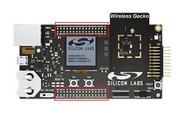
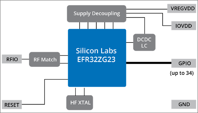
The repository implements Geographic Location CC in an end-device such as the Z-Wave Alliance ZRAD project or on a Silicon Labs Devkit using a QWIIC I2C based GPS receiver like the M8Q from Sparkfun.
See the repo for more examples and details. The official Z-Wave Alliance specification update with GeoLocV2 is currently being reviewed and expected to be published in one of the 2025 releases.
Heat Map Examples
One of the drivers to create GeoLocV2 is to generate heat maps of the RF Range for testing Z-Wave Long Range. In previous Unplugfests we use a very subjective measurement of having an LED stop blinking when out of range. Often the LED would pause, but then start blinking again, then stop so it was difficult to determine the exact edge of RF range. With GeoLocV2 we can map the exact locations where the device is when it is able to make 100% error free, encrypted connection.
The Silicon Labs Works With 2024 conference produced a fantastic video (featuring DrZWave! – well, I have a supporting role) demonstrating GeoLocV2 in action on a motorcycle! Skip to minute 43:40 (about 3/4 of the way thru the video) to see the video.

Below is a heat map from a skydiving test that we will be producing a video in the near future. Z-Wave Long Range demonstrated 2.7 mile range – straight UP! A ZRAD was used as the controller running Z-Wave JS and a small Javascript program to extract the GeoLoc data from a commercial Z-Wave device using a PCB antenna stuffed inside a fanny pack of the jumper. This example demonstrates the need for the Altitude in the specification.

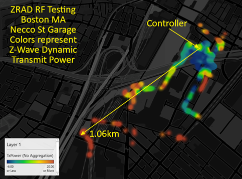
Below is a heat map with the color showing the transmit power needed to make an error free connection which ranges from -6dBm to +20dBm. The test took place in a residential neighborhood outside Boston Massachusetts where the ZRAD controller is in a wood frame building on the second floor and a ZRAD End Device was driven around the neighborhood reaching a general 500m and a maximum of over 1.4km. This demonstrates the dynamic power of Z-Wave Long Range where it saves battery power anywhere within 100 meters but can extend the range thru many obstacles to over a kilometer.

Be sure to attend the upcoming Z-Wave Unplugfest and Summit in Barcelona Spain in February 2025 or the one in Carlsbad CA in April to see GeoLocV2 in action.