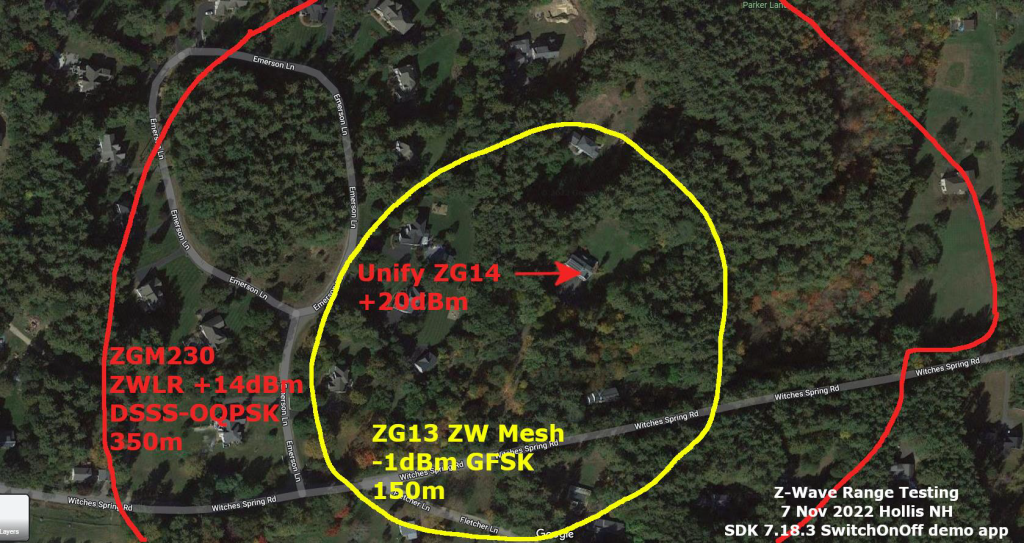
Z-Wave Long Range (ZWLR) claims to reach over 1 mile, but does it actually reach that far in the real world? The answer is YES. However, in the real world we are operating inside a building and surrounded by trees and other buildings. The more important answer is how does ZWLR do in a building and in an neighborhood? I recently captured some data in my home town just outside of Boston which shows ZWLR easily reaches the entire yard and then some.
The first thing to understand about the RF range of Z-Wave are the different power levels used by regular Z-Wave (ZW) and ZWLR. I’m comparing the values used in the US but the rules are different in each region. In the EU the max transmit power is +13dBm with regular Z-Wave which is why the range in the EU is so much further than in the US. But let’s focus just on the US for now.
RF Transmit Power
There are 3 levels of Z-Wave RF transmit power in the US:
- -1dBm – Regular Z-Wave GFSK modulation – 12mA
- +14dBm – ZWLR DSSS-OQPSK modulation – 41mA
- +20dBm – ZWLR DSSS-OQPSK modulation – 92mA
The huge increase in transmit power is why ZWLR has over double the range of ZW. The reason ZWLR can transmit at such high power levels is that the spread spectrum modulation spreads that energy across a 1MHz carrier compared to the narrow band FSK of ZW. The FCC allows the transmit power to be as high as +30dBm but that would be a challenge for a battery powered device as it would likely need half an amp of current!
Why are there two power levels for ZWLR? The RF transmit power is matched to the power supply of the typical use case. The ZGM230 module is limited to +14dBm since it is most often used in battery powered devices where even the 41mA current is a bit challenging for low-cost batteries. The +20dBm ZG23 is best suited to mains-powered devices to get the maximum range. ZWLR utilizes dynamic RF power so for nodes that are close enough, the battery life is extended by using only enough RF power to reliably reach the controller. the dynamic power algorithm is built into the Z-Wave protocol so you don’t have to manage it at all.
RF Range at Home

The Yellow circle is the regular Z-Wave mesh range with a controller in a room on the 2nd floor. My home is surrounded by large pine trees which limit the range. Using 700/800 series Z-Wave chips there are no dead spots anywhere in my home. I still have a few 100 series devices, several 300 series and a lot of 500 series devices many of which need the mesh to hop to reach my controller. This demonstrates the increasing range of each generation of Z-Wave. If I were to upgrade all of my devices there would be little if any routing using regular ZW.
The Red circle shows over double the range of regular Z-Wave at +14dBm. The combination of higher transmit power and increased sensitivity due to the spread spectrum modulation yields a strong signal over my entire neighborhood. Note the bump on the right side caused by the open field and the swampy area with a lot fewer trees. Each wall or tree or building reduces the range but ZWLR easily reaches well beyond the end of the yard. I couldn’t test 20dBm because there just isn’t enough open space for me to measure it! So I moved to a building in the center of town.
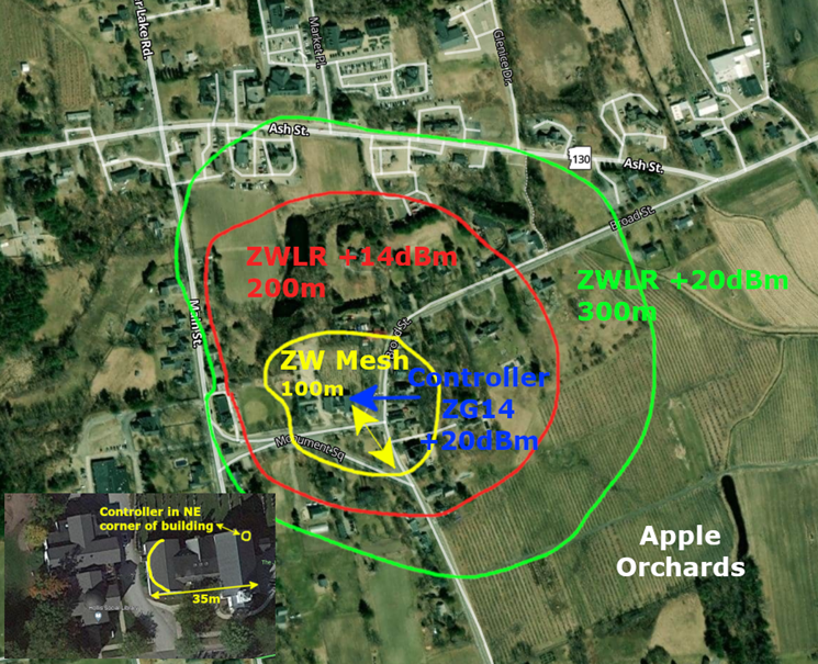
RF Range in Town

The photo above shows the relative range of all three transmit powers. In this case the controller is in the upper right corner of a commercial building as shown in the inset in the lower left. Regular Z-Wave is not quite able to reach the two rooms at the far end of this 35m building. But ZWLR easily reaches the entire building and well beyond. Each step, +14 and then +20 roughly doubles the range in this typical application where there are still a number of trees and buildings reducing the signal. Recall from middle school geometry that the circumference of a circle is 2*pi*radius or roughly 6*radius. On the day I performed this test, I doubled my daily step goal and walked over 20,000 steps!
In both of these measurements the line is roughly where full 2-way, fully secure, supervision encapsulated Basic Set commands were being sent to a battery powered SwitchOnOff sample application using SDK 7.18.3. I used a Raspberry Pi running Unify and a small python program to send Basic Set On/Off commands every half second to the Dev Kit and then noted where the LED stopped blinking. Once I stepped a few paces back toward the controller, the two devices would resync and the blinking would restart. Z-Wave is very adept at re-connecting to devices that are at the margin of the RF range.
During the Z-Wave summit earlier this month we did a live demonstration of the range versus the transmit power. While regular Z-Wave reached well beyond the conference center, it couldn’t quite get to the adjacent hotel. ZWLR however reliably reached the hallways in the hotel thru the concrete and glass of each building.
How to Set Tx Power
For regular Z-Wave the transmit power is normally set pretty close to the maximum of -1dBm. There are two configuration parameters to set based on the results of FCC testing. See INS14664 in Simplicity Studio for details. For ZWLR, setting the transmit power easier. Simply set APP_MAX_TX_POWER_LR in zw_config_rf.h to either 140 for +14dBm or 200 for +20dBm but that only works if the EFR you are using supports +20. The 700 series EFR32ZG14 supports +20 but the balun has to be wired to +3.3V to have enough power to reach +20. The ZGM130/230 are both limited to just +14. The EFR32ZG23 part number chooses either +14 or +20 – EFR32ZG23B0X0F512 – If the X is 1 it’s +14, if 2 then +20.
One last configuration setting is to make sure ZWLR is enabled. This is in zw_region_config.h and all you need to do is set it to REGION_US_LR. The protocol code completely handles everything relative to ZW or ZWLR for you so just a 3 character change enables ZWLR.
Conclusion
All new Z-Wave devices for the US market should support Z-Wave Long Range. The low-latency (no routing), high reliability and long range make it a must for any new product. The question is +14 or +20? All controllers should be using the SoC (EFR32ZG23A/B020) to get the most range. The SoC requires calibration of the crystal for each unit as described in UG517. The module (ZGM130/ZGM230) are limited to +14 only and come pre-calibrated from Silicon Labs and thus are ideal for end devices that are battery powered. The SoC should be used for any mains-powered end device since the current draw is not an issue but be careful to specify the right part number with the 020 in it.