Z-Wave Mesh Priority Routes Explained

Z-Wave is a wireless mesh protocol with over two decades of real-world learning built into the latest version. While the other new wireless protocols are still writing the specification for their mesh network, Z-Wave has learned a thing or two over the past twenty years. Z-Wave is a Source Routing protocol where the Primary Controller of the network keeps track of the best paths thru the network to/from any point to any other point.

Z-Wave limits the number of hops thru the mesh to four hops to bound the routing calculations to something an inexpensive microprocessor can handle. These four hops quickly explode into a huge number of routing combinations as the size of the network grows to more than a few dozen nodes. The trick is to pick the optimal set of routes to get from one node to the next. This is where the two decades of learning have proven to be the key to Z-Waves robust delivery.

Source Routing Introduction

The 500 series Appl. Prg. Guide section 3.4 describes the “routing principles” used in Z-Wave. While this is a 500 series document the 700 series uses the same algorithm with a few minor enhancements. The key to source routing is that the Primary Controller (PC) calculates the route from Node A to Node B. Each node along the way does not need to know anything about the routing, it just follows the route in the packet header determined by the PC. When an end node needs to talk to the PC or any other node, the PC will send the end node four routes to get from Node A to Node B. As a final backup route, Node A can send out an Explorer Frame asking all nodes within radio range if they can help get the message to Node B. If a node is able to help and the message is delivered, this route becomes what is known as the Last Working Route (LWR). Node A will then use the LWR route whenever it needs to talk to Node B.

There are a total of five routes stored in any node to get to any other node. Note that routes are calculated and stored only if a node is Associated with another node. Since most nodes usually only talk to the PC (Associated via the Lifeline – Association Group 1), that is the only set of routes it stores. The primary controller has the full network topology but still follows the same basic algorithm when sending a message to a node. The five routes are held in a list for each destination. If a message is delivered successfully, that route is moved to the top of list and is called the Last Working Route (LWR). The LWR will be used from now on until it fails for some reason. RF communication is fraught with failures and they will happen occasionally so the LWR often changes over time. When the LWR route fails, the list is pushed down and once a working route is found, it is placed at the top of the list as the new LWR.

Application Priority Routes

Application Priority Routes (APR) are special routes the Application can assign to a node to get messages from Node A to Node B. They are called “Application” Priority Routes because the protocol never assigns APRs, only the APPLICATION can assign APRs. Typically the application is the software that is talking directly to the PC – a Hub application like SmartThings or Hubitat or one of the many other Hub applications. The protocol assumes that someone smarter than it (meaning an expensive powerful CPU with tons of memory) can figure out a better route from A to B than it can. The protocol places the APR at the top of the 5 routes in the list and always keeps it there. Even ahead of the LWR. While this gives the application a great deal of power, it also means the application can make a mess of routing and inadvertently cause a lot of latency. Large Z-Wave networks tend to have dynamic routing which is why the LWR has been the key to the routing algorithm – Once you find a working route, keep using it!

PCC Icon for APR

I generally don’t recommend using APRs since the routing tends to be dynamic and it is often best to let the protocol find the best route. However, adding Direct Route APRs where the node will talk back to the Hub directly rather than routing thru other nodes can reduce latency. This sometimes solves the problem where the LWR gets stuck with a multi-hop route when the Hub could reach it directly. A direct route is the fastest way to deliver messages and multi-hop messages often can have noticeable delay to them. When a motion sensor detects motion in a dark room, speed and low-latency are central to maintaining a high WAF factor and quickly turn on a light.

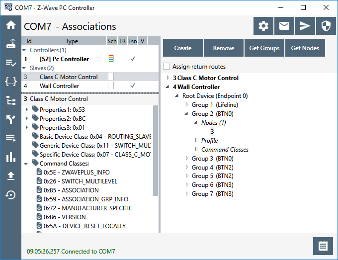
Using the PC Controller to Assign APRs

The PC Controller has a section called “Setup Route” which has a number of ways of setting up various routes.

There are 5 different types of Routes that the PCC can setup:

# RouteDescriptionSerialAPI Command
1Return RouteAssigns 4 controller computed routes between 2 nodesZW_AssignReturnRoute() (0x46)
2Priority Return RouteAssigns an Application Priority Route between 2 nodesZW_AssignPriorityRoute() (0x4F)
3Set Priority RouteAssigns an Application Priority Route from the controller to a nodeZW_SetPriorityRoute() (0x93)
4SUC Return RouteAssigns 4 controller computed routes from the end node to the controllerZW_AssignSUCReturnRoute() (0x51)
5Priority SUC Return RouteAssigns an Application Priority Route from the controller to an end nodeZW_AssignPrioritySUCReturnRoute() (0x58)
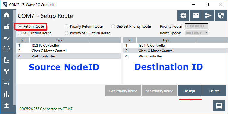
1. Return Route

Return Route assigns four routes to the source node (left) to reach the destination node (right). Anytime an Association is made from one node to another, a Return Route MUST be assigned so the source knows how to reach the destination. The most common application is a motion sensor turning on a light without going thru the hub. For example; a motion sensor (Node 10) is associated with the light (Node 20) and then a call to ZW_AssignReturnRoute(10,20,SessionID) will send four messages to node 10 with four different routes to get to node 20. In this case the Application does NOT specify the route to be used but lets the Primary Controller calculate the best 4 routes. The source node can still use Explorer Frames to find a route if all four fail. During inclusion a controller should always assign return routes to the end node back to the PC so the end node has routes for any unsolicited messages (or use the SUC Return Route below). If the network topology changes significantly (nodes added or removed), then all the return routes of every node in the network should be reassigned to ensure the optimal route is used.

2. Priority Return Route

Priority Return Route is used to assign an Application Priority Route between two nodes. The only time I recommend using this command is to assign a priority route back to the controller to use no routing assuming the node is within direct range of the controller. It is too easy to mess up the routing with this command so in general I do not recommend using it.

3. Get/Set Priority Route

Get or Set the Application Priority Route (APR) the primary controller uses to reach a node. Since the node will use the same route to return the ACK this will become the LWR for the end node so both sides will use this route first. Note that this route is not set at the end node, only the controller will use this route. If the end node needs to send a message to the controller it will use this route if it is the LWR otherwise it will use one of its own assigned routes. Note that you can set the speed in this command. Be careful not to blindly set the speed to 100kbps. If the nodes in the path are older or the destination is a FLiRS device then they may only support 40kbps. Old 100 series nodes can only do 9.6kbps but they can still be part of the mesh. Note that you can GET the priority route (0x92) with this command if one has been assigned. If a Priority Route has not been assigned then the current LWR is returned.

The only application of Set Priority Route I recommend is to force nodes close to the controller to always try direct communication first. In this case, you would Set Priority Route with all zeroes in the route. This tends to make scenes that turn on a lot of lights run quickly so there is less popcorn effect. If a scene with a lot of lighting nodes fails to deliver to one of the nodes, the PC then searches thru routes to find a new route, the routed route becomes the LWR and the controller will continue to use the LWR until that route fails for some reason. By assigning a Priority direct route the controller will always try the direct route first. Since 700 series devices usually have excellent RF, if the controller is in the same room or at least on the same floor as the lights it is controlling, then the direct routes will minimize the popcorn delay. However, if the lights are not in direct range, it will just delay everything making the popcorn worse! So be careful in assigning APRs! Don’t make things worse.

Set the Application Priority Route to Node 2 to direct (no hops) at 100kbps

The example above shows how to assign an APR direct route to Node 2. The function call for this would be: ZW_SetPriorityRoute(2, 0, 0, 0, 0, 3); Every time the PC sends a message to node 2 it will always try this direct route first, if that fails to ACK, then it will use the LWR then the other return routes it has calculated.

APR to Node 6 thru 5->4->3->2 at 100kbps

The example above shows an extreme example where we force routing to be the maximum number of hops of four. This is a handy way to test your product with a lot of routing! A zniffer trace of a message looks like:

Node 1 sending Basic Set to Node 6 via 1->5->4->3->2->6

The function call for this would be: ZW_SetPriorityRoute(6, 5, 4, 3, 2, 3); The PC will always use the route to send a message to node 6, if it fails, it will try the LWR and then the other return routes and finally an Explorer Frame.

4. SUC Return Route

The SUC Return Route is a shorter version of the Assign Return Route (1. above) which simply sets the Destination NodeID to be the SUC which in most cases is the Primary Controller.

5. Priority SUC Return Route

The Priority SUC Return route is again a short version of the Assign Priority Return Route (2. above) which automatically sets the Destination NodeID to be the SUC. It is generally easier to simply use the normal Return Route commands (1. aan 2. above) and fill in the Destination NodeID as the PC (which is usually the SUC) than to use these two commands.

Conclusion

The techniques explained here are not intended for general Z-Wave users but instead for the Hub developers and end-device developers. Since these are low-level commands and not something a user typically has access to, you’ll have to pressure your Hub developer to follow these recommendations.

Hub developers MUST assign return routes ANY time an Association is made between two nodes especially back to the Hub immediately after inclusion and assignment of the Lifeline. If the network topology changes such as when a node is added or removed, it may be necessary to reassign ALL of the routes to all nodes to take advantage of the new routes or eliminate nodes that no longer exist. Be careful assigning Priority routes especially if a node in a Priority Route is removed from the network. If a now non-existent NodeID is in an APR, the node will try really hard using the APR with the missing node before finally giving up using the LWR. This will result in annoying delays in delivering commands or status updates. Z-Wave will still deliver the message, but only after you’ve banged your shin into the coffee table in the dark because the motion sensor is still trying to send thru the missing NodeID in the Application Priority Route.

Detecting RF Jamming

Cheap RF Transmitter

All wireless protocols can be jammed often using an inexpensive battery powered transmitter. The protocol doesn’t even have to be radio frequency (RF) based as Infra-Red (IR) and any other communication medium that travels thru the air can be jammed by blasting out noise in the same spectrum as the protocol. Think of a busy street corner where you and a friend are having a conversation and a firetruck with their sirens blareing go by. Your conversation stops because your friend simply can’t hear you above all the noise. The same thing can happen in Z-Wave where a “bad actor” brings a small battery powered transmitter and blasts out RF in the same frequency bands that Z-Wave uses. In this post I’ll explain how to jam Z-Wave and also how to detect and inform the user that jamming has occurred.

Security System Requirements

Jamming applies primarily to security systems. After all, if someone wants to jam your house from turning on the kitchen lights at night, what’s the point other than to get a laugh when you bang your knee into the table? Z-Wave has enjoyed a great deal of success in the security system market. Z-Wave is interoperable, easy to use, low-power and the mesh networking protocol means users or installers don’t have to be concerned with getting everything to talk to everything else as the protocol automatically handles (mostly) everything. Security systems however are very concerned about jamming to the point that Underwriters Laboratory has a specification for it. UL1023 is the US standard for Safety Household Burglar-Alarm Systems.

The reality of the situation for a security system is that it is unlikely a burglar will try to bypass your security system by jamming it. Burglars are simply not that tech savvy. The FBI doesn’t even track the numbers of burglaries via jamming – one would assume because the number is essentially zero. A burglar will simply bash in a window or door or more often simply walk in an unlocked door. However, if it’s easy enough and cheap enough, a burglar might just try! CNET demonstrated just how easy it is to use a $3 transmitter to bypass a popular security system using a cheap RF transmitter. Regardless of the reality of the situation, the bad press of having an easy to jam security system can crater a company.

Anti-Jamming Techniques in Z-Wave

Z-Wave was designed from day one to be robust and reliable. The very first requirement for robustness is to acknowledge that the device receiving the message did in fact receive it. Every Z-Wave message is acknowledged (ACK) otherwise the sender will try again using different mesh routes or other RF frequencies. After several retries, the protocol will give up and the application can then decide if it wants to try even more ways to deliver the message. If the message is not very important (like a battery level report), the application can just drop it. If a sensor detects smoke! Then the application will continue trying to get this life-safety message thru in every way possible for as long as possible.

Z-Wave requires two-way communication – all messages are acknowledged

Here’s a list of the techniques Z-Wave uses for robustly delivering messages:

  • Z-Wave
    • All frames are Acknowledged
    • Multiple mesh routes
    • Frequency Hopping – Two frequencies – 3 different baud rates (in US)
    • RSSI Measurements indicating jamming
    • Supervision CC confirms decryption & data integrity
  • Z-Wave Long Range
    • All frames are Acknowledged
    • Dynamic TX Power
    • Frequency hopping to alternate channel
    • RSSI Measurements indicating jamming
    • Supervision CC confirms decryption & data integrity

Even with all these different measures in place, it is still possible to jam Z-Wave. But it’s not cheap nor is it easy. But let’s give it a try for fun!

Jamming Z-Wave

Jamming Z-Wave starts with a Silicon Labs Z-Wave Developers Kit and Simplicity Studio. However, these kits are not cheap costing at least $150 for just one. It may be possible to find a cheap 900MHz transmitter but you will need two of them and they must have the ability to tune them to the specific Z-Wave frequencies of 908.4MHz and 916MHz in the US. These are not going to be $3 battery powered transmitters and they require a significant amount of technical knowledge. Neither cheap nor easy so I think we’re pretty safe from your typical burglar.

Z-Wave uses two channels (frequencies) in the US: 908.4MH for 9.6 and 40Kbps and 916MHz for 100Kbps. Z-Wave Long Range (ZWLR) also has two channels but uses spread-spectrum encoding which spreads the signal out across a band of frequencies centered at 912MHz and 920MHz. By using two channels Z-Wave is frequency agile which makes it harder to jam since you need two transmitters instead of just one. The spectrum analyzer plot below shows four DevKits blasting all 4 channels at once.

Z-Wave jamming all four frequencies – 912 & 920 are Z-Wave Long Range

Creating the jammer firmware utilizes the RailTest utility in Simplicity Studio V5. Select the DevKit in the Debug Adapters window, click on the Example Projects & Demos tab then check the Proprietary button. The only example project should be the “Flex (RAIL) – RAILtest application”. Click on Create and use the defaults. The default frequency will state it is 868 but ignore that as the Z-Wave modes are all built into RailTest and do not need to be configured. Once the project is created, click on Build and then download to a devkit. Right click on the devkit in the Debug Adapters window and click on Launch Console. Click on the Serial 1 tab then click in the command box at the bottom and press ENTER. You should get a RailTest prompt of >.

Once you're at the RailTest prompt, enter the following commands:

rx 0                 -- disables the radio which must be done before changing the configuration
setzwavemode 1 3     -- Puts the radio into Z-Wave mode
setpower 24 raw      -- 24=0dbm radio transmit power - valid range is 1 to 155 but is non-linear
setchannel 0         -- ch0=916 ch1=908.4 ch2=908.42 - ZWLR ch0=912 ch1=920
setzwaveregion 1     -- EU=0, 1=US, 13=US Long Range
Do one of the following 2 commands:
SetTxTone 1          -- narrow band Carrier Wave - unmodulated
SetTxStream 1        -- Pseudo-Random data - modulated and in ZWLR uses Spread Spectrum (DSSS) 
Use the same command with a 0 to turn the radio off
Remember to "rx 0" before changing any other configuration values

RAILtest is a powerful utility and can do all sorts of things beyond just Z-Wave. The radio in the Silicon Labs chips are Software Defined Radios, they can be customized to many common frequency bands. It is easy to create customized versions of RAILtest that will transmit a carrier wave (CW) or a modulated signal at just about any frequency band, not just Z-Wave. But that’s more complex than I have time to discuss here.

Now that we know how to jam, how do we detect it and inform the user that jamming is taking place? Detecting jamming takes place at both ends of the Z-Wave network, the Controller and the End Device. Let’s first look into the End Device which in a security system is typically a motion sensor or a door/window sensor.

End Device Jamming Detection

Most end devices are battery powered so they spend most of their time sleeping and are completely unaware of any RF jamming that might be taking place. Only when motion is detected or a door is opened will the sensor wake up and find the radio waves being jammed. The best way to check for RF jamming is to first try to send a message. When the message fails to be acknowledged, then start looking to see if jamming is occurring.

The Z-Wave Application Framework (ZAF) handles sending the message and eventually calls a callback to report status. The callback comes through EventHandlerZwCommandStatus() which will be called several seconds after sending the message. The protocol tries various mesh routes, power levels and baud rates which takes time so be sure to stay awake long enough to receive the callback. The callback returns the TxStatus variable which is typically TRANSMIT_COMPLETE_OK (0x00) which means the message was delivered. But if jamming is taking place and the radio was unable to go through it, you’ll get a TRANSMIT_COMPLETE_FAIL (0x02). This status is different than the TRANSMIT_COMPLETE_NO_ACK (0x01) which means the message was not acknowledged which is usually because the destination is offline but could also be due to jamming.

The next step is to verify that jamming is taking place by getting the current Received Signal Strength Indicator (RSSI) level by queuing the EZWAVECOMMANDTYPE_GET_BACKGROUND_RSSI event . The RSSI is a simple value in dB of the strength of signal at the radio receiver when its not actively receiving a frame. In normal operation, this value should be around -100dB. Every environment is different so the threshold for the radio being jammed needs to be a value that is significantly higher than the average value. This is particularly tough in dense housing like apartments where perhaps every unit has a Z-Wave network. This results in a relatively high RSSI average. The key here is you can’t use a simple hard-coded threshold for jamming detection based on RSSI. Instead you must average the RSSI values across a long time-span (typically hours).

Z-Wave Notification of Jamming

The next step after detecting jamming has occurred is to notify the hub. But if the jamming is still in progress, how can the notification get thru? Naturally you can’t get thru while the jamming is still happening. The trick is to keep trying and hope that the jamming is short term. The problem is that a battery powered sensor can’t keep trying constantly as it will run out of battery power perhaps in just a few minutes. You must manage battery power and at the same time keep trying with a longer and longer timeout between attempts. At some point the jamming should end, perhaps hours after the initial break-in but the jammer will eventually run out of battery power.

The Z-Wave Notification Command Class has a pre-defined value for RF Jamming – Notification Type of Home Security (0x07) with an Event of RF Jamming (0x0C) and the current average RSSI level. This notification is a critical notification so it should be wrapped in Supervision Command Class to guarantee it has been delivered and understood by the controller.

Sample Code

The code below first checks the TxStatus, if is not OK, then the RSSI level is checked by queuing the GET_BACKGROUND_RSSI event. Once the RSSI is sampled, the function will be called again with the switch going thru the GET_BACKGROUND_RSSI case below. This section of code then compares the current RSSI level with a background RSSI level and if the current level is above it then the SendRFJamNotificationPending global variable is set. When a frame is able to get thru then the pending RF Jam notification is sent since it appears the jamming has ended. This ensures the Hub is informed that there was jamming so the Hub can then decide if it needs to inform the user. The basics of the algorithm are coded here:

... 
static void EventHandlerZwCommandStatus(void)
...
switch (Status.eStatusType)    
...
    case EZWAVECOMMANDSTATUS_TX:  // callback from attempted message delivery
...
            
        if (pTxStatus->TxStatus != TRANSMIT_COMPLETE_OK) { // failed to deliver - check RSSI
            EZwaveCommandType event = EZWAVECOMMANDTYPE_GET_BACKGROUND_RSSI;
            QueueNotifyingSendToBack(g_pAppHandles->pZwCommandQueue, &event, 0); // Queue GET_RSSI
        } else { // message delivered OK
            // more cleanup happens here...
            if (SendRfJamNotificationPending) { // Is there a pending Jam Notification?
               SendRfJamNotificationPending=false;   // Send it!
               void * pData = PrepareNotifyJamReport(&zaf_tse_local_actuation);
               ZAF_TSE_Trigger((void *)CC_NotifyJam_report_stx, pData, true);
            }
        }
...
    case EZWAVECOMMANDSTATUS_GET_BACKGROUND_RSSI:  // only called if failed to deliver a message
        if (Status.Content.GetBackgroundRssiStatus.rssi > BackgroundRSSIThreshold) {    
            // Set a global to send an RF Jamming Notification which will be sent when jamming ends
            SendRfJamNotificationPending=true;
            SendRfJamNotifRSSI= Status.Content.GetBackgroundRssiStatus.rssi;
        }
... // Not shown are application level retries and various other checking

Now that we have jamming detection enabled on the end-device side, let’s look at the controller end of the communication.

Controller Jamming Detection

Obviously the main thing the controller needs to do is react to a jamming notification from an End Device. The ultimate action the controller performs is left to the controller developer but clearly the end user should be notified that jamming has been detected. But that notification needs to be qualified with enough information about the average RSSI noise level to avoid false jamming detection notifications.

If the jammer is way out at 200+ meters, the RSSI level may not jump up significantly as measured by the controller. Thus, it is important to react to the End Device notification of jamming. However, the controller must poll the RSSI level at regular intervals to determine if jamming is taking place nearby. The question is how often should it poll and when to react to a sudden change in the RSSI level? There is no definite answer to this question other than “it depends” and it depends on a lot of different factors. Typically, the RSSI should be sampled a few times per minute – perhaps every 30 seconds. If a value seems unusually high, perhaps sample several more times at a much faster rate to confirm that the RSSI has jumped and its not glitch. Like the End Device case, the average RSSI value needs to be calculated across a fairly long time frame (minutes to perhaps an hour) and when there is a change from the average value then the user should be notified.

ZW_GetBackgroundRSSI

The SerialAPI function ZW_GetBackgroundRSSI() (0x3B) will return three or four bytes of RSSI values for the various channels supported by the controller. This function can be sent to the Z-Wave controller frequently as it does not cause any delays in the radio. It does use UART bandwidth so it can’t be called too frequently or it may interfere with normal Z-Wave traffic. The polling function should coded with a low priority so it is only sent when the UART has been idle for a few seconds to avoid collisions with Z-Wave radio traffic. The one-byte RSSI values are coded as shown in the table below.

RSSI values returned by the ZW_GetBackgroundRSSI():

HexDecimal (2s Comp)Description
0x80-0xFF-128 – -1Measured RSSI in dBm
0x00-0x7C0 – 124Measured RSSI in dBm
0x7D125RSSI is below sensitivity and cannot be measured
0x7E126Radio saturated and could not be measured as it is too high
0x7F127RSSI is not available

Typically a 700 series Z-Wave controller will measure about -100dBm when the airwaves are fairly quiet. During a transmission the RSSI is often about -30dBm when the node is within a few meters of the controller.

TxStatusReport

The TxStatusReport is returned after a frame was transmitted which includes several fields with a variety of RSSI measurements. There is a Noise Floor of the sender as well as a NoiseFloor of the receiver. The RSSI values can be monitored during normal Z-Wave traffic without polling. It is best to use these values while Z-Wave traffic is taking place and to temporarily pause the polling while the Z-Wave UART is busy. Once the UART is idle, resume RSSI polling.

Missing Heartbeats

Another aspect of jamming is that battery powered devices typically send a “heartbeat” message every hour so the controller knows for sure the device is online and working (mostly that the battery isn’t dead). The controller should be keeping track of how long it has been since the last time a battery powered node has checked in and if it has missed two or at most three heartbeats, the controller should inform the user (or the installer) that the device is offline and unable to communicate. If the battery was already low, then the battery is probably dead. If the battery was fine, then there is a possibility that the device is being jammed.

Controlling FLiRS via Associations

Frequently Listening Routing Slaves (FLiRS) are a class of Z-Wave devices that are battery powered but wake up every second to check if there is a message waiting for them. FLiRS were initially used for door locks. Door locks have fairly large batteries since they have to move a mechanical device to lock or unlock a door. Typically this is four AA batteries. With this fairly large battery storage, we still need a method to talk to the lock but can’t stay awake all the time as the batteries would only last a week or so. FLiRS to the rescue! FLiRS lets the lock remain asleep 99% of the time and wake up very briefly once per second and listen for an always-on device to be sending a “Wakeup-Beam”. The Beam is a constant transmission of the NodeID and a 1 byte hash of the HomeID telling that specific node to fully wake up and be ready to receive a message. This low-power mode allows Z-Wave devices to run for years on a battery but still be ready to lock or unlock within 1 second.

Z-Wave door locks first appeared in 2008 but since then FLiRS mode has found uses in other battery powered devices. The next most popular FLiRS device are thermostats. Older heating systems which rely on a simple mercury switch have only 2 wires and do not need power. To upgrade these simple switches to a smarthome Z-Wave thermostat means a battery powered device has to last for years on a single set of 3 or 4 AA batteries. FLiRS to the rescue again! Since a user is fine if it takes a few seconds to change thermostat settings, FLiRS is the ideal way to extend battery life and still be connected to the internet.

Recently we’ve had a number of window shades come to market based on FLiRS. Window shades have the challenge that often there is no power near the window so they need to be battery powered. Sometimes a solar cell can help keep the batteries fresh but the FLiRS mode is key to long battery life. Controlling the shades with Alexa is the favorite mode to show off your smarthome – “Alexa, set shades to 0%”. The challenge comes in if you want a battery powered wall switch or some other device to directly control the shades. This is usually done using a Z-Wave Association where the wall switch is “associated” with the shade and then controls the shades without the Hub being involved. This is faster and in some cases can be done without a Hub at all. The trick is getting the wall switch to send the Beam to wake up the shades. Setting the Association is insufficient. A Return Route has to be sent which will tell the wall switch to send a beam.

Association

The first step in directly controlling the shades from a wall switch is to assign the shade to an Association Group. Using the PC Controller application to add the association is done by selecting the destination in the left window and then choosing the Association Group to add it to in the right window. In this case I’ve added the shade NodeID=3 to the Wall Controller NodeID=4 Group 2 which will send a BASIC_SET when I press button 0.

Note the checkbox for Assign Return Routes. Initially I’ll leave this unchecked. This is what many Hubs fail to do properly – set the Return Route anytime an association is made. So what happens when I press Button 0?

The Wall Controller (nodeID=4) sends the Basic Set command 3 times but the Shade (nodeID=3) does not ACK. The Wall Controller tries two more time with Explorer Frames trying enlist anyone else in the network to deliver the frame. But they all fail. Why? Because the Shade is asleep waiting for a Wakeup Beam.

Assign Return Route

To get the Wall Controller to send a FLiRS Wakeup Beam we have to tell it to send one! That is done by assigning a Return Route. In the PC Controller the easy way to do that is to simply check the box in the Association window. The way a Hub should do it is with the SerialAPI command ZW_AssignReturnRoute( SourceNodeID, DestNodeID, callback) which is SerialAPI command 0x46 (see section 4.4.4 of INS13954). We can do this manually in the PC Controller using the Setup Route window shown here. The key is to select the Return Route radio button, then in the left pane select the Wall Controller (the Source NodeID) and in the right pane select the Shade (the Destination), then click on Assign.

When you click on assign you’ll see 4 frames sent from the Hub to the Wall Controller which includes the information to send a FLiRS Beam to the Shade.

These Assign Return Route frames are not officially documented but you can pretty quickly figure out the details of the data. Once the Return Route frames have been delivered to the Wall Controller, it will then send a Wakeup Beam to the Shade before sending the Basic Set.

Here we can see the Shade ACKing the Basic Set in line 72 so the Wakeup Beam did its job and woke up the shade so it was ready to receive the basic set and close the shade.

Z-Wave Long Range Impact

Z-Wave Long Range supports FLiRS types of devices but it doesn’t support Associations. Z-Wave Long Range is a star network so all communication has to go thru the hub. Then the hub forwards the message on to the FLiRS device after Beaming to wake it up. There is no way for a Long Range end device to send a frame to another end device, it has to go thru the controller.

Time vs. Clock vs. Time Parameters Command Classes Explained

Introduction

Door locks, thermostats and other Z-Wave devices often need to know at least the time and day of the week. In many cases they need to know the full date and time to enable a lock User Code when a renters code is valid or set the thermostat into energy save mode. These devices need a way to determine the current date and time to within a few seconds of accuracy.

Z-Wave provides three different command classes (CC) for getting various parts of the date/time. Time Command Class is mandatory for all Gateways. Unfortunately, not all gateways support it yet, so most devices need to support one of the other command classes for use with older hubs. The question then is how is a device supposed to get the current date/time so the schedule can operate properly?

Time CC – Recommended

Time command class is described in SDS13782 (Z-Wave Management Command Class Specification). Time CC is mandatory for all Z-Wave Plus Gateways and thus is the recommended method for a device to set its clock to the current local date and time. Time CC Version 2 adds time zones and daylight savings time support if desired however V1 provides the necessary data in most cases.

The Z-Wave specification recommends having an association group to identify the time server node however the Gateway is expected to have an accurate time reference so using the Lifeline is acceptable.

The Time CC does NOT have a date/time SET command. Thus, the hub cannot set the date/time and instead must wait for the device to GET it. When a device is included in a network, it must send a Time GET command within the first few minutes to accurately set its internal clock. The device should then periodically send a Time GET to ensure the internal clock remains accurate to the local time. Note that for certification purposes a device CONTROLs Time CC, it does not SUPPORT it. The Hub is required to SUPPORT Time CC.

Time Parameters CC – Optional

The Time Parameters command can SET/GET/REPORT the year, month, day, hour, minute & second of the UTC time. However, it does not set the time zone which must be done via the Time CC V2. Thus, Time Parameters CC relies on the hub to send the current UTC time but the device can also send a GET and adjust its internal clock to match the one from the hub. However, this requires support on the hub software which is not mandatory so not all hubs will be able to provide the current date/time.

Clock CC – NOT Recommended

Clock command class is sent by a Hub and can set the local weekday and time. Thus, it only supports a 7-day schedule since it cannot set the date, just the day of the week. Typically, the Hub would send a Clock Set as part of inclusion in the network. Since the clock on the device will drift, the device must periodically send a Clock Get to the Hub and to maintain time accurately. This method is NOT recommended. However, on some old hubs this is the only method available.

Recommended Time Setting Algorithm

  1. Wait for Inclusion into a Z-Wave Network
  2. Wait for Security negotiation to complete
  3. Send a Time CC DATE GET
  4. Wait for a Time CC DATE REPORT for ~30s
  5. If DATE REPORT arrives, Send a Time CC TIME GET and wait for ~30s
    1. if the Time REPORT arrives then the date/time is now set and use Time CC for future clock adjustments
    1. Exit the search for the local time
  6. If Time CC DATE REPORT times out:
    1. Retry 2 more times with random delay of a few minutes between each retry
  7. During steps 3-6, If a Time Parameters CC SET or a Clock CC REPORT is received, use those to update the date/time but if a Time CC report arrives use Time CC
  8. Send a Clock CC GET
    1. If a REPORT arrives within ~30s then use Clock CC GET to update the date/time
  9. If CLOCK fails
  10. Send Time Parameters CC GET to get the current date/time
  11. If those fail, there is no source for the current date/time, disable all scheduling features

Depending on the accuracy of the local clock circuitry, the functioning time setting command class should be used to update the local clock at a sufficient rate to match the desired settings. Typically, this would be once per day assuming a 100ppm or better 32Khz crystal is used for the 700 series low frequency external crystal oscillator (LFXCO).

Conclusion

End Devices should send a Time CC Date/Time GET shortly after inclusion in a Z-Wave network and then periodically send Date/Time GETs based on the accuracy of the real-time clock circuitry. Updating at 3:10am ensures the clock will be accurate to daylight savings time should be sufficient for a low-cost 32kHz crystal. The algorithm above works for just about any hub that has at least minimal support for time keeping.

How to OTA a co-processor via Z-Wave

You have a second MCU or other data files you want to update using Over-The-Air (OTA) via Z-Wave. How can you reuse the Bootloader firmware to verify the signature and decrypt the data?

The code to verify and decrypt the file already exists in the bootloader and is known good. Reusing the existing bootloader code is smaller and safer than re-inventing the wheel – or in this case encryption.

The attached project is a modified Z-Wave Door Lock Key Pad sample application that demonstrates how to OTA code/data other than the Z-Wave firmware. OTA of the Z-Wave firmware works in the sample application already – but first the encryption keys MUST be generated. See https://www.silabs.com/community/wireless/z-wave/knowledge-base.entry.html/2019/04/09/z-wave_700_ota_ofe-i00M on how to generate the keys. See the two .BAT files in the comments section which will run all the necessary commands for you. They are also included in this .sls file in the KEYS directory. You MUST create your own project keys to OTA either the Z-Wave Firmware or any other data.

To OTA other types of files you need to start with a binary file. Most microprocessor development environments will output a binary file so use that instead of a HEX file. If you have an Intel hex or Mototola S record file, use a utility like SREC_CAT to convert it to a binary file. SREC_CATcan convert just about any file type into any other file type. If the file is more than 200K bytes, you will need to break the file into 200K or smaller files and OTA each, one at a time. Doing that is beyond the scope of this project. Note there is no need to encrypt the file. We will be using Commander to sign and encrypt it using the keys generated here.

Theory of Operation:

Changes to the SSv4 DoorlockKeyPad sample project are indicated with the comment “AKER” – search for these to find what changed. You can also diff the files with a fresh copy of the DoorLockKeyPad sample app from SSv4. Most of the code to support OTA of an external processor is in this file. A few changes have been made to ota_util.c in ZAF_CommandClasses_FirmwareUpdate but these are expected to be included in a future release of the SDK (currently tested on 7.13). 

Commander is used to generate a pair of public and private keys. The private key is then programmed into every device to be OTAed. Commander then encrypts and signs the binary file and wraps it with bootloader tokens. The gbl file is downloaded, the signature checked and the encrypted data is then passed to a callback function 64 bytes at a time. You then have to store the data or pass it to the external MCU. This example simply prints the data out a UART.

Procedure:

Step 1: Generate the keys

There two .BAT files in the KEYS directory for this project. These are windows script files. For other platforms you can easily convert them to the platform specific commands. See the comments in the files for more details. In a windows shell type:
   GenGblToken.bat
This will use Commander to generate a project set of keys in the files vendor_*.*. Only execute this command ONCE. The same keys are used for the duration of the project. If you change the keys then you cannot OTA the devices as the keys no longer match.

Step 2: Program the key into a devkit and every DUT

Each device manufactured must have the private key programmed into FLASH. Use the PgmToken.bat to program the key into a target device connected via USB. Note that EVERY unit manufactured must have these keys programmed into it.

Step 3: Generate the .gbl file

Create the .gbl file from the binary file using the following command:
   commander gbl create <OTA_FileName>.gbl –metadata <BinaryFile> –sign vendor_sign.key –encrypt vendor_encrypt.key
The –metadata option will wrap the binary data with the necessary tokens for the bootloader to parse the data. Do not use the –compress option. If the data needs to be compressed, use your own algorithm for that. There are 3 sample binary files in the KEYS directory – a small .WAV audio file, a large .M4A audio file and a PNG image file. Use the command above to wrap the file with the necessary tokens for OTA.

 Step 4: OTA the .gbl file

Use the PC Controller or other application to send the gbl file over Z-Wave. Once the entire file has been sent and the CRC checked to be good, the FinishFwUpdate function is called to begin processing the image. Note that in the PCC you have to first GET the Current Firmware, then select the Target: 1 to download the metadata. Then click on UPDATE and the OTA will begin. Connect a terminal to the VCOM port of the WSTK to view the data streaming down during the OTA. Once all the data is sent down, the signature is checked and the decrypted data is sent out the UART. This is where you would need to change the code to store the data instead of printing it out the UART.

Step 5: Verify the Signature and pass in the callback function

The bootloader_verifyImage() function is called and the metadataCallback function is passed in. bootloader_verifyImage first returns a zero if the signature matches. If the signature fails an error value is returned giving some details on why it failed. The time to verify the signature can be fairly long depending on the size of the image so the watchdog timer is disabled during the processing.

Step 6: MetadataCallback passes blocks of 64 bytes of the decrypted data

The function passed in to bootloader_verifyImage is called with a pointer to the data and the number of bytes in each block. The size of the block can vary up to 64 bytes. In this example the data is simply printed out the UART. In your application you would replace this function with code to store the data as needed on the other MCU or external NVM.

Step 7: Reboot

It is recommended to reboot after the image data has been stored to ensure the FLASH is cleaned up properly. The current demo however does not reboot.

Note: This is an SSv4 SDK 7.13 sample but the same concepts should work in SSv5. The changes to ota_util.c will be folded into the SDK in a future release but for now those changes are necessary.

The code example can be downloaded from the Silicon Labs web site at: https://www.silabs.com/community/wireless/z-wave/knowledge-base.entry.html/2020/09/23/ota_a_co-processororotherdataviaz-wave-GDap

Z-Wave Works With Amazon, Google, Samsung, Apple, Comcast Virtual Conference

Silicon Labs is hosting what was intended to be an in-person conference in Austin Texas but is now a virtual online conference on IoT ecosystems – the Works With Smart Home Developer Event September 9-10. The best part is it is now FREE to attend any of the in-depth technical sessions and you don’t have to wear a mask. The downside is that we don’t get to experience all that great music down in Austin – well, there’s always next year!

Virtual IoT Works With EcoSystems from Google, Amazon, Apple for Z-Wave development engineers
https://workswith.silabs.com/

I am hosting the Z-Wave track and will be making several presentations including a detailed look at Silicon Labs latest release of Simplicity Studio V5 which just came out yesterday. We’ll also have presentations on developing Z-Wave Smart Hubs and Z-Wave Certification. I’ll also be describing some IoT failures – you learn more from your failures than your successes. We have speakers and engineers from all of the ecosystem partners, not just Silicon Labs folks. Learn from the experts from across the industry!

What is Works With 2020? The smart home developer’s virtual event where you will have the opportunity to interact with our ecosystem partners from Amazon, Google, Samsung, and Z-Wave to connect devices, platforms and protocols and be able to immerse yourself in keynotes, a panel discussion on Project CHIP, hands-on, and technical sessions led by smart home engineers who are building the latest advanced IoT devices. The Works With event is live, all-online, free of charge, and you can join from anywhere around the world.

Works With Z-Wave Apple, Google, Amazon, Samsung IoT SmartHome conference 2020

Click here to Register Today and feel free to forward to the rest of your team.

Here’s an overview of what you won’t want to miss:

Specialized Engineer-Led Tracks – Educational sessions and technical training designed for engineers, executives, developers, business development and product managers.

Hands-On Workshops More than 12 workshops and hands-on sessions to give you experience, knowledge and confidence to develop and accelerate smart home development.  

One-on-One Developer Meetings – Schedule a meeting with Silicon Labs or an ecosystem partner to get 1:1 technical guidance.

Join me in September and learn how to smoothly get your IoT device plugged into any and all of the ecosystem partners. Register today, it’s totally free and you can join from anywhere in the world. See you September!

Z-Wave for the Smart Home Presentation

I’m giving a presentation on Z-Wave where you can ask questions and get answers about the opening of the Z-Wave specification among other topics. There are more Tech Talks scheduled and several recent topics were recorded. Follow the links below.

      Logo     Hero       Good news! We have added new Tech Talks. Join us on Tuesdays and Thursdays for live virtual, technical discussions hosted by a lead engineer with time allocated for your questions. We’ll cover topics like battery optimization with BG22, using Z-Wave for your Smart Home Solutions and more. You don’t want to miss these next talks.

Register by clicking here: Tech Talks:
Z-Wave Smart Home Solutions by Doctor Z-Wave
Tomorrow April 23 at 4 p.m ET

Battery Optimization with BG22
Tues, April 28 at 3 p.m. CT
Max Performance on BLE – Simultaneous Connections, Beacons and Scanning
Thurs, April 30 at 3 p.m. CT
SubGHz Proprietary and Connect Software Stack
Tues, May 5 at 3 p.m. CT
How to Measure and Debug Network Performance – Using Silicon Labs Network Analyzer
Thurs, May 7 at 3 p.m. CT

Zniffer File HowTo

Z-Wave developers have a handy tool for debugging firmware and Z-Wave network issues called the Zniffer. The Zniffer consists of two parts, the first is a USB dongle with special firmware and the second is the Windows program. You can’t buy just a Zniffer USB dongle (they come as part of some of the developers kits) but you can make one out of a standard UZB. You can even make a SuperZniffer as described in my previous blog posting. The Zniffer program is included in the Simplicity Studio IDE tools for developing Z-Wave products.

Zniffer traces are INVALUABLE when submiting a support case to the Silicon Labs Z-Wave support web site. I am an Field Applications Engineer so I often review Zniffer traces captured by developers who have questions or are reporting bugs. The problem is that many times I get a support case that says “Zniffer trace attached – what is problem?” and the Zniffer trace is several hundred megabytes with dozens of Z-Wave networks and maybe one hundred Z-Wave nodes captured across days of time. Talk about the proverbial needle in a haystack! So I am asking everyone to follow a few rules BEFORE attaching a Zniffer trace to a support case.

Zniffer File Rules

Before attaching a Zniffer file for Z-Wave support to review, include the following:

  1. The HomeID of the network with the problem
  2. The NodeID of the Z-Wave node that demonstrates the problem
  3. The line number or the date/time of the where the problem occurred (or a range)
  4. The Security Keys of the Z-Wave network
  5. A clear and concise description of the problem, what should have happened, what didn’t happen, what you believe is wrong

ZnifferHowTo1

HomeID

The HomeID of a Z-Wave network is a 4 byte, eight digit hexadecimal number that uniquely identifies a single Z-Wave network. Only devices with the same HomeID can talk to each other. In a development environment there are often dozens or even hundreds of Z-Wave networks in range. Remember the Zniffer captures every network in the air. Please do not filter the HomeID when saving out the Zniffer file as there may be critical interactions with other network or even noise that will be filtered out if you save only the matching HomeID. We can always filter by HomeID when displaying the network on our PC but we can’t see the data if its not in the file.

NodeID

The NodeID of the node that is displaying the issue has to be identified. You might have dozens of nodes in the network who are all talking at once so we need to know which one is the one with the problem. Please include details of the device as well such as what type it is (binary switch, thermostat, sensor, battery powered, etc) . Ideally if you can include the device within the zniffer file that will tell us just about everything we need to know as the NIF will be exchanged and the interview will take place.

Date/Time

Each transaction in the Zniffer trace is identified by a line number on the left side or the date/time. Indicating the line number or date/time or a range of these will help us navigate the potentially huge Zniffer file and quickly zoom in on the problem. Wading thru days of Zniffer data to finally find the interesting bit is just wasting our time and yours.

Security Keys

If you are working with Secure devices you MUST include the security keys. Without the security keys the data is encrypted and it is all just meaningless ones and zeroes and we can’t help you. Now that all devices are required to be secure, the key file is critical. The Zniffer trace has to include the SPAN table update as without the SPAN table we again cannot decrypt the message. The easiest way to be sure the SPAN is included is to add the device-under-test (DUT) to the network while capturing the Zniffer trace. The other option is to power cycle the DUT which will usually cause the DUT and the controller to exchange Nonces to resynchronize the SPAN table and we can once again decrypt the messages in the Zniffer.

To extract the security keys, join the PC Controller to the Z-Wave network. Be sure to enable all levels of security by providing the S2 DSK of the PC Controller. Once joined to the network, the keys can be saved to a file using the procedure below:

ZnifferHowTo2

The filename is the HomeID.txt which in the case above is FFE5B5C9.txt and contains:

9F;C592557B5F99DDC9BDD12D0D926BAFE5;1
9F;31944FE8F8DE2330E79741313A949190;1
9F;18FD847446AFD7E410B2BCF8912BC632;1
98;C65D55C44FB2156635CA07A48D362AD3;1

To decyrpt the messages in the Zniffer, just click on Load Keys and enter the directory for the file. Then all the messages are decrypted and we can help you solve your problem.

Z-Wave 700 Series Announcement

The long awaited 32-bit ARM based Z-Wave transceiver chip has finally been officially announced. The 700 series announcement is on the home page of the Silicon Labs web site so this is a big deal for SiLabs and Z-Wave. The companies joined forces just eight months ago and we already have a major advance in Z-Wave technology.

Z-Wave 700 Press Image

What’s New?

The 700 series is a major improvement to Z-Wave for both consumers and developers. For consumers, the lower power and longer radio range means more reliable communication and longer battery life. For developers the main advantage is we’ve finally moved beyond the 1980s 8051 8-bit CPU with very limited debug capability into a modern 32-bit ARM CPU with full serial wire debugging capabilities. We can FINALLY single step thru code instead of having to use PRINTF!

700 Series Features:

  • Longer RF range
    • 150% in the US and 200% in the EU due to improved RF sensitivity and increased transmit power in the EU
  • Lower Power = Longer Battery Life
    • Improved semiconductor technology and a faster CPU yields significant battery life improvement and 10 year coin cell operation
  • Lower Cost – Worldwide Support
    • Improved RF blocking means the country specific SAW filter is not needed saving cost and making a single SKU for worldwide operation
    • No external serial memory is required and OTA firmware update is now mandatory
  • Easier Product Development
    • Integrated Debug Environment (IDE) with full ARM debug, single step, trace, and energy profiler speeds product development
  • 100% Interoperable and Backwards Compatible
    • The 700 series is fully interoperable with all mesh-networked Z-Wave devices all the way back to the pre-100 series Z-Wave devices

When Can I Get One?

If you already signed up for a free Beta devkit, then one should be on its way in the next few weeks. Devkits have begun shipping but quantities are limited and will take until the end of January before all the Beta samples are shipped. The Beta signup closed back on October 1st so if you missed the deadline you’ll have to wait until later in Q1 to request one from your Silicon Labs salesperson. The official “general availability” (GA) release is the end of Q1 at which time the datasheets, chips, devkits and software will be released at the 7.xx full release version. Datasheets require an NDA until the GA release.

You can get started today using the Simplicity Studio IDE and begin developing code and explore the SDK. The software is free and can be downloaded from here.

My Initial Thoughts

I’ve had a 700 series Beta DevKit for a few weeks now working with our Alpha release partners to get some early feedback. We’ve had some hiccups and the firmware needs more work but the silicon is solid. I have joined my 700 series devkit to my home and it communicates fine with my very early pre-100 series Z-Wave light switches attesting to the ongoing commitment Z-Wave has to be fully interoperable and backwards compatible.

Z-Wave Summit Fall 2018 Philadelphia

The Z-Wave Summit is usually held only once each year in the USA and it is not to be missed. I’ll give a brief overview of what was discussed at the summit in the short post below. But if you didn’t attend in person, you missed the most valuable aspect of the summit which is the chance to meet and talk to other Z-Wave developers. This year the summit was hosted by Bulogics in the city of brotherly love,  Philadelphia PA. Bulogics is a Z-Wave certification house so they know everything about Z-Wave and how to have a good time!

2018ZWaveSummitMitch.jpg

Summit Notes

The 700 series was officially “revealed” at the summit with many presentations talking about the new ARM based Z-Wave transceiver. The summit has over 140 attendees from 70 companies not including all the Silicon Labs and Alliance employees. This is the largest attendance of a summit to date and reflects the rapidly growing world of Z-Wave.

Matt Johnson, IoT Sr. VP, described the roadmap for multiprotocol chips which include Z-Wave, zigbee, BLE and Wifi as well as proprietary protocols. For the immediate term though the focus is on getting the 700 series shipping. The real key for Z-Wave is the interoperability and certification ensuring every Z-Wave device can communicate with every other device.

Z-Wave product manager Johan Pedersen presented the important improvements in the 700 series over the 500 series:

  • ARM M4 32-bit CPU
  • 150% RF range improvement in the US and more in EU/Asia
  • Lower power and faster wakeup time making coin cell operation a reality
  • Lower cost due to elimination of the external NVM & SAW
  • Single HW build for all regions due to elimination of the SAW filter
  • Longer battery life with 1.8-3.6V operation
  • Serial debugging

By far my main interest as a developer is that we finally have a real CPU with an M4 and serial debugging so I can finally single step my code and figure out where I went wrong!

The next natural question of course is when will the 700 series be a reality? The answer is “soon”. Ugh. Developers kits are supposed to be available soon and the parts will be shipping in early 2019.

Technical Track

On the second day of the summit the groups are split between marketing and technical geeks like me. More presentations on things like the new Z-Wave Plus V2 requirements which will go into effect with the 700 series release. The V2 requirements significantly ups the bar for support for various command classes with the goal of making Z-Wave devices to fully inform the hub of their capabilities. There should be little or no custom coding to support most V2 devices – the device will tell you everything it can do.

The presentation by Alex Capecelatro, founder of Josh.ai, described the future of voice control which sounds amazing. Alex described just how hard voice control really is and has a long way to go before it really works the way we all want it to. I liked his quote from the New York Times: “We overestimate what technology can do in 3 years but underestimate what can be done in 10 years”. Z-Wave has come a long way in the dozen years it’s been around.

Configuration Command Class

2018summitERI gave a presentation on Configuration Command Class Version 4 and all the wonderful things it can do. The most notable point is that 2/3rds of the Z-Wave Plus certified devices have at least one Configuration Parameter. Yet many hubs have no way of modifying or displaying to the user the current value of parameters. Z-Wave Plus V2 mandates support for Configuration Command Class V4 for both hubs and devices so you need to get busy! My presentation title is: “The Chicken vs Egg is over: Moving Your Product to Configuration Version 4” which can be downloaded from this link: Z-WaveAlliance2018EricRyherd.

Interoperables Band

Once again the band The Interoperables played at the evening get together at a local brewery. These guys are really good for having only practiced a couple of times!

2018ZWaveSummitInteroperables

DrZWave joins Silicon Labs

That’s right, I have officially joined Silicon Labs as an FAE covering the Eastern US. I can be contacted at drzwave@Silabs.com.