Z-Wave developers have a handy tool for debugging firmware and Z-Wave network issues called the Zniffer. The Zniffer consists of two parts, the first is a USB dongle with special firmware and the second is the Windows program. You can’t buy just a Zniffer USB dongle (they come as part of some of the developers kits) but you can make one out of a standard UZB. You can even make a SuperZniffer as described in my previous blog posting. The Zniffer program is included in the Simplicity Studio IDE tools for developing Z-Wave products.
Zniffer traces are INVALUABLE when submiting a support case to the Silicon Labs Z-Wave support web site. I am an Field Applications Engineer so I often review Zniffer traces captured by developers who have questions or are reporting bugs. The problem is that many times I get a support case that says “Zniffer trace attached – what is problem?” and the Zniffer trace is several hundred megabytes with dozens of Z-Wave networks and maybe one hundred Z-Wave nodes captured across days of time. Talk about the proverbial needle in a haystack! So I am asking everyone to follow a few rules BEFORE attaching a Zniffer trace to a support case.
Zniffer File Rules
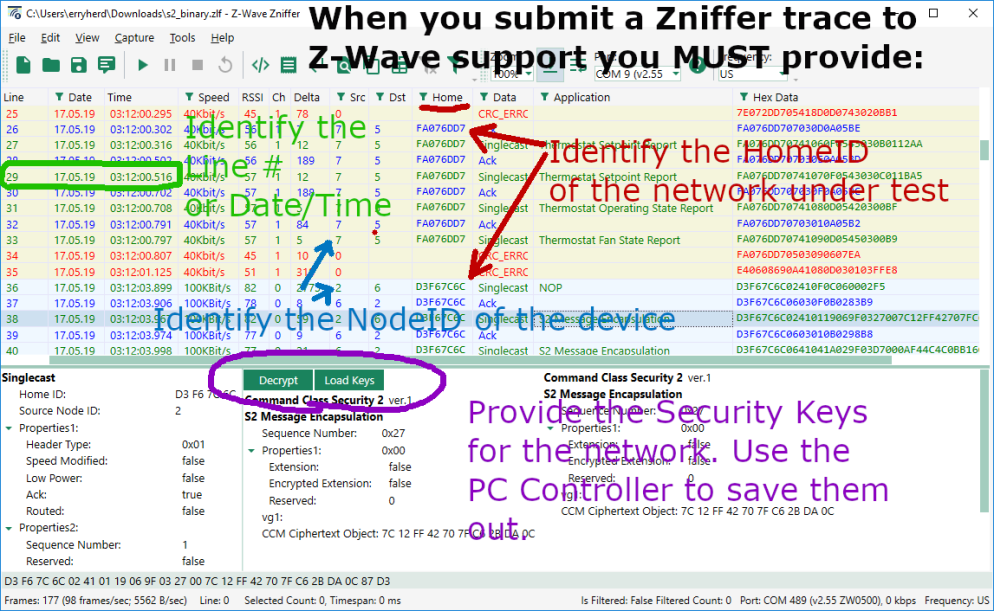
Before attaching a Zniffer file for Z-Wave support to review, include the following:
- The HomeID of the network with the problem
- The NodeID of the Z-Wave node that demonstrates the problem
- The line number or the date/time of the where the problem occurred (or a range)
- The Security Keys of the Z-Wave network
- A clear and concise description of the problem, what should have happened, what didn’t happen, what you believe is wrong
HomeID
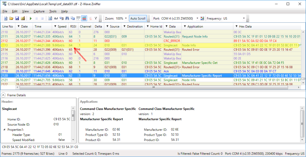
The HomeID of a Z-Wave network is a 4 byte, eight digit hexadecimal number that uniquely identifies a single Z-Wave network. Only devices with the same HomeID can talk to each other. In a development environment there are often dozens or even hundreds of Z-Wave networks in range. Remember the Zniffer captures every network in the air. Please do not filter the HomeID when saving out the Zniffer file as there may be critical interactions with other network or even noise that will be filtered out if you save only the matching HomeID. We can always filter by HomeID when displaying the network on our PC but we can’t see the data if its not in the file.
NodeID
The NodeID of the node that is displaying the issue has to be identified. You might have dozens of nodes in the network who are all talking at once so we need to know which one is the one with the problem. Please include details of the device as well such as what type it is (binary switch, thermostat, sensor, battery powered, etc) . Ideally if you can include the device within the zniffer file that will tell us just about everything we need to know as the NIF will be exchanged and the interview will take place.
Date/Time
Each transaction in the Zniffer trace is identified by a line number on the left side or the date/time. Indicating the line number or date/time or a range of these will help us navigate the potentially huge Zniffer file and quickly zoom in on the problem. Wading thru days of Zniffer data to finally find the interesting bit is just wasting our time and yours.
Security Keys
If you are working with Secure devices you MUST include the security keys. Without the security keys the data is encrypted and it is all just meaningless ones and zeroes and we can’t help you. Now that all devices are required to be secure, the key file is critical. The Zniffer trace has to include the SPAN table update as without the SPAN table we again cannot decrypt the message. The easiest way to be sure the SPAN is included is to add the device-under-test (DUT) to the network while capturing the Zniffer trace. The other option is to power cycle the DUT which will usually cause the DUT and the controller to exchange Nonces to resynchronize the SPAN table and we can once again decrypt the messages in the Zniffer.
To extract the security keys, join the PC Controller to the Z-Wave network. Be sure to enable all levels of security by providing the S2 DSK of the PC Controller. Once joined to the network, the keys can be saved to a file using the procedure below:
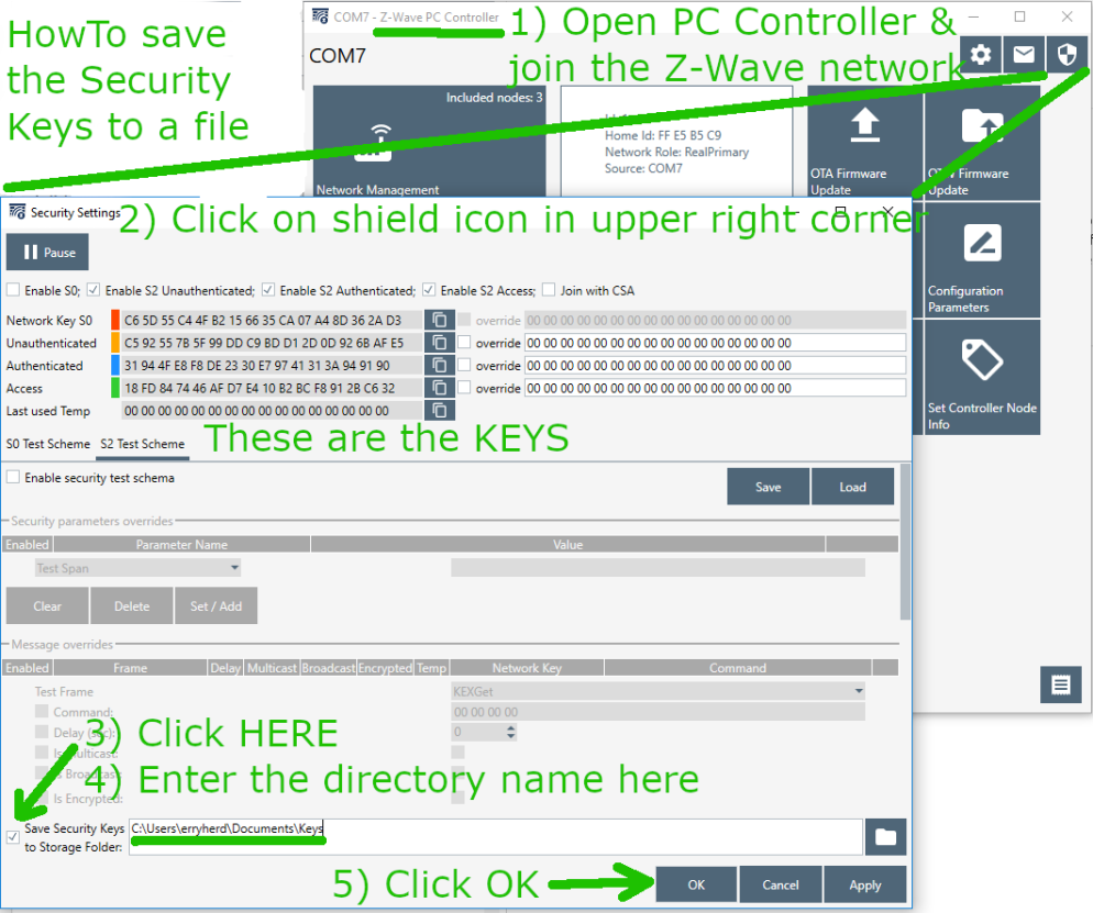
The filename is the HomeID.txt which in the case above is FFE5B5C9.txt and contains:
9F;C592557B5F99DDC9BDD12D0D926BAFE5;1
9F;31944FE8F8DE2330E79741313A949190;1
9F;18FD847446AFD7E410B2BCF8912BC632;1
98;C65D55C44FB2156635CA07A48D362AD3;1
To decyrpt the messages in the Zniffer, just click on Load Keys and enter the directory for the file. Then all the messages are decrypted and we can help you solve your problem.
 The Z-Wave team in Copenhagen resides in this modest building. Danes love to bicycle to work or take the excellent train/bus system. Only a few travel via car unlike those of us in the US who just love sitting in traffic for hours. The food in Copenhagen is wonderful with plenty of international choices as well as the Danish favorites. My hotel room is more of a spaceship pod than a boring room with the Danish penchant for efficient minimalism. The view of the windmills in the distance and the quaint classic European architecture are beautiful.
 Virtually all embedded systems must run 24 x 7 x 365 x many many years without ever being rebooted. Since there is no one there to “press the reset button” if the device fails, the watchdog timer is there to do just that. The 500 series Z-Wave chips from Silicon Labs have a watchdog timer and the example code provides a very minimal use of the watchdog timer. However, the minimal use in the example code is not sufficient to provide a robust watchdog for embedded Z-Wave devices. This post explains some rules and methods to code a robust watchdog timer.
 This diagram shows the Watchdog timers value which is constantly counting up. Every time the Watchdog is “kicked”, the counter is reset to zero. Somewhere in your code the ZW_WatchDogKick() routine is called which resets the watchdog timer. Sometimes this reset condition happens on a nice regular basis, sometimes it happens at varying times as shown by the level of the timer. The key is the timeout threshold has to be longer than any normal operating condition. If a fault condition occurs, the timer keeps on counting up until the threshold is reached and then the system is reset. When the watchdog timer fires, the Z-Wave chip goes thru a full reset just as if power had been removed and reapplied. Your embedded system is back up and running as if nothing had happened.
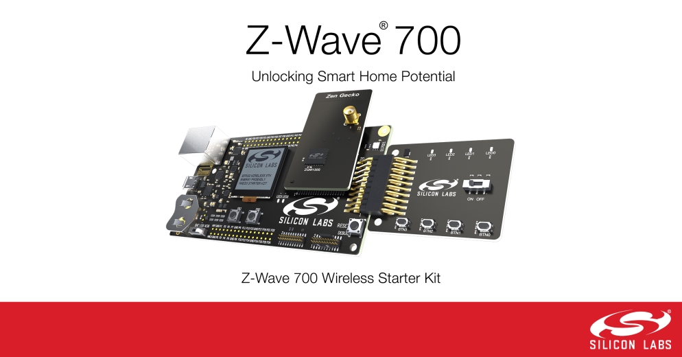

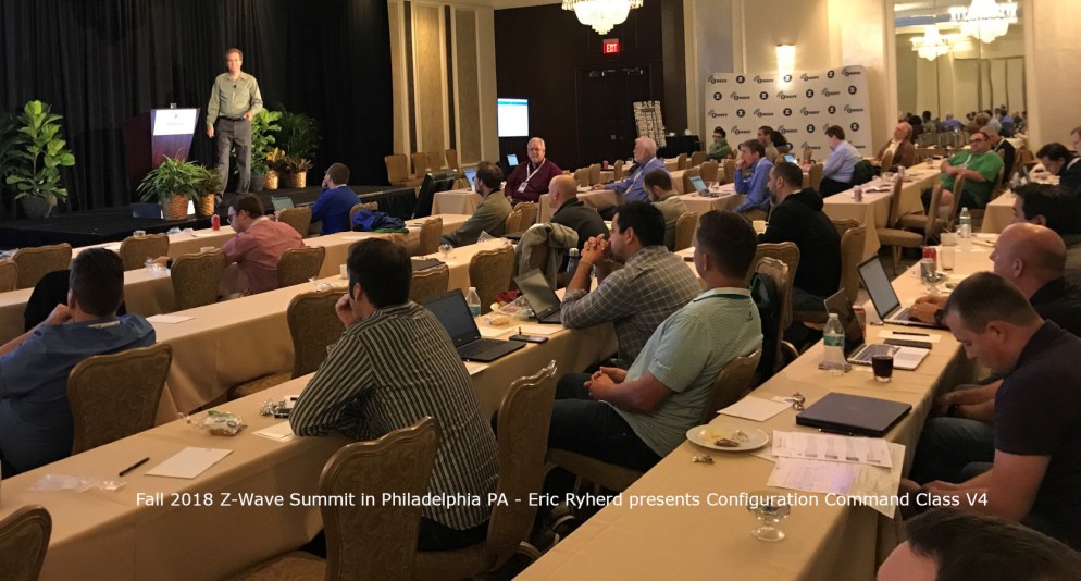 I gave a presentation on Configuration Command Class Version 4 and all the wonderful things it can do. The most notable point is that 2/3rds of the Z-Wave Plus certified devices have at least one Configuration Parameter. Yet many hubs have no way of modifying or displaying to the user the current value of parameters. Z-Wave Plus V2 mandates support for Configuration Command Class V4 for both hubs and devices so you need to get busy! My presentation title is: “The Chicken vs Egg is over: Moving Your Product to Configuration Version 4” which can be downloaded from this link:
 A simple method to observe the instructions our C code generates for our little 8051 CPU is to use the simulator built into the Keil C compiler. By default the Keil IDE does not have a simulator when using the Silicon Labs sample projects so you have to assign one. Right click on the project then select “options” then click on the “Debug” tab. Then enter “s8051” into the CPU DLL box as shown here. You can now click on Debug->Start/Stop Debug Session or press <CTL>F5. This will enter the Keil Simulator for the 8051. One thing to understand is that this simulator does NOT understand the bank switching of the Silicon Labs version of the 8051 used in the 500 series. Unfortunately you can’t debug code much using this simulator as any bank switching doesn’t work. But it will work well enough to debug small snippets of code and of course to see what you code turns into.
 Once the debugger opens in the IDE, click on the line of code you are interested in and the Disassembly window (use View->Disassembly if its not visible) will take you right to the line of code you are interested in as shown here. Note that the C source code is mixed in as comments in the assembly code. This helps guide you to match the C code to the assembly code which can be a little convoluted depending on the optimization the compiler has applied. You can see here that the Do-While has turned into our desired DJNZ single instruction loop.
 IoT Device Testing Best Practices by Eric Ryherd
 There were nearly 200 attendees at the Summit – a significant increase over last year. One of the main purposes of the summit is to learn what’s new in Z-Wave and what Silicon Labs is planning for the future. The most important news at this year’s summit is the 700 series which was
  The Summit isn’t all work all day even though the days are long and filled with lots of technical information. This summit had an evening at the
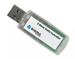 You have to make one out of a
 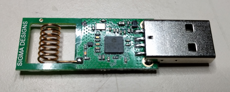 The first step is to pry open the UZB enclosure. Use a small flat head screwdriver to pry it open along the USB connector. There are pins that hold the two halves together. Be careful not to break off the pins as we’ll use the enclosure with the Zuper Zniffer.
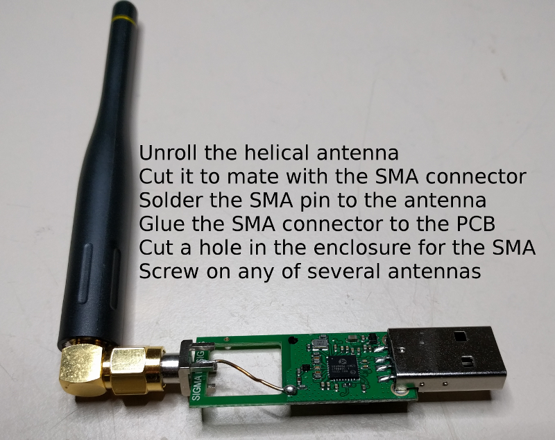 Next unroll the helical antenna and cut it off so it just reaches the end of the PCB. Place the SMA connector on the end of the PCB and solder the antenna wire to the center pin of the SMA as shown above. You can solder the ground pin of the SMA to the PCB ground but it doesn’t seem to make much of a difference. Cut the enclosure to make room for the SMA connector to stick out the end and then snap it back on. Then screw on any SMA antenna and try it out. I typically get 3 to 5 more dB as reported in the Zniffer software RSSI column. This should be nearly 10X more range. There are so many antennas to choose from once you have an SMA connector so experiment and find one that works for you. You can even use a Yagi antenna which would then make the Zniffer highly directional.
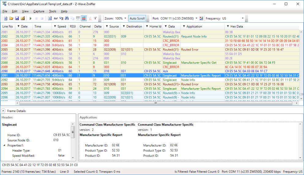
 Click
Click  The presentation goes into detail on each of these topics so I won’t duplicate the information here. I also go thru several failures of devices I’ve been working with. You learn more from failures than you do when everything just works. Feel free to comment and let me know what topic you’d like to see for next years summit.
 The Summit isn’t all work all day though the days are long and tiring. Tuesday evening was a reception at