I have a simple problem – I have a sensor module with a simple uart interface that I need to connect to my Z-Wave project. Ther UART is used to configure the sensor and then it will send sensor readings at regular intervals. Simple right? Turns out the path is not so simple for Silicon Labs Simplicity Studio. Let’s go step by step through my journey to implement this interface on the Silicon Labs EFR32ZG23.
Typical UART Driver
Embedded engineers expect the UART driver to consist of the following functions:
- UART_INIT(Baud, data_bits, stop_bits, parity, options)
- Initialize the uart with the desired baud rate and options
- UART_GETCHAR()
- UART_PUTCHAR(char)
- UART_PUTS(string) – nice to have
- Put a string of characters – simply calls UART_PUTCHAR for each char in the string
Since most MCUs contain multiple UARTs, these basic functions need a pointer to which UART is being accessed. Typically a pointer to the desired UART is added to each function and then these are wrapped in macros with the UART number in the macro name such as: UART0_INIT and EUSART2_PUTCHAR. Extensions from these basic functions generally involve buffering data or being blocking or non-blocking (IE: polled or interrupt driven) and selecting GPIOs. Pretty standard stuff, easy to understand, easy to use, does what you expect with minimal code and effort.
Note that these functions are independent of the hardware. The engineer does not need to read the manual (RTFM) to be able to use them. If any of the fancy features of the UART are needed, the engineer will RTFM and then write the appropriate registers with the appropriate values to enable the desired feature. Hopefully the manual is detailed enough for the engineer to get the desired function to work without a lot of trial and error (unfortunately this is rarely the case). But less than 1% of the engineers will ever need those fancy features which is why these simple functions are the foundation of most UART drivers.
Now follow my efforts to interface this simple UART sensor with an EFR32 with the expectation there will be an API similar to the Typical UART Driver described above.
Step 1: What do I need? – 5 minutes
RTFM of the sensor to find the basic UART interface requirements. The manual states it uses a baud rate of 256000, 1 stop bit, no parity. The manual was clearly written by someone who did not have English as their first language as it also states “the sensor uses small-end format for serial communication” which I’m assuming means little-endian? Could it mean the bit ordering of each byte is LSB first? The limited information in the manual means I’ll be doing some trial-and-error debugging. The manual is thin, only 23 pages so it only took about five minutes to find this information.
Step 2: What does the EFR32 have? – 10 minutes
I’m using the Silicon Labs EFR32ZG23 which has three EUSARTs (enhanced UART) and one USART. All four have lots of features including SPI as well as normal UART functionality. The datasheet describes EUSART0 as being able to operate in lower power modes and USART0 (apparently not “Enhanced”) as having IrDA, I2S and SmartCard features. None of these extra features are needed for my application. EUSART0 and EUSART2 have limited GPIO connections thus I don’t want to use either of those as I want the maximum pinout flexibility offered by EUSART1. The EFR32ZG23 datasheet is 130 pages but searching for “UART” (then “USART” since UART has only 1 hit) got me this much information in about 10 minutes. Later I stumbled on the fact that the EUSARTs have a 16 byte hardware FIFO on both the send and receive side vs. the UART which just has two byte. This is deep in the xG23 Reference Manual and not mentioned in the datasheet. A 16 byte FIFO means the EUSART is a winner! Why bother including the USART?
Step 3: Open Simplicity Studio and Explore APIs – 60 Minutes
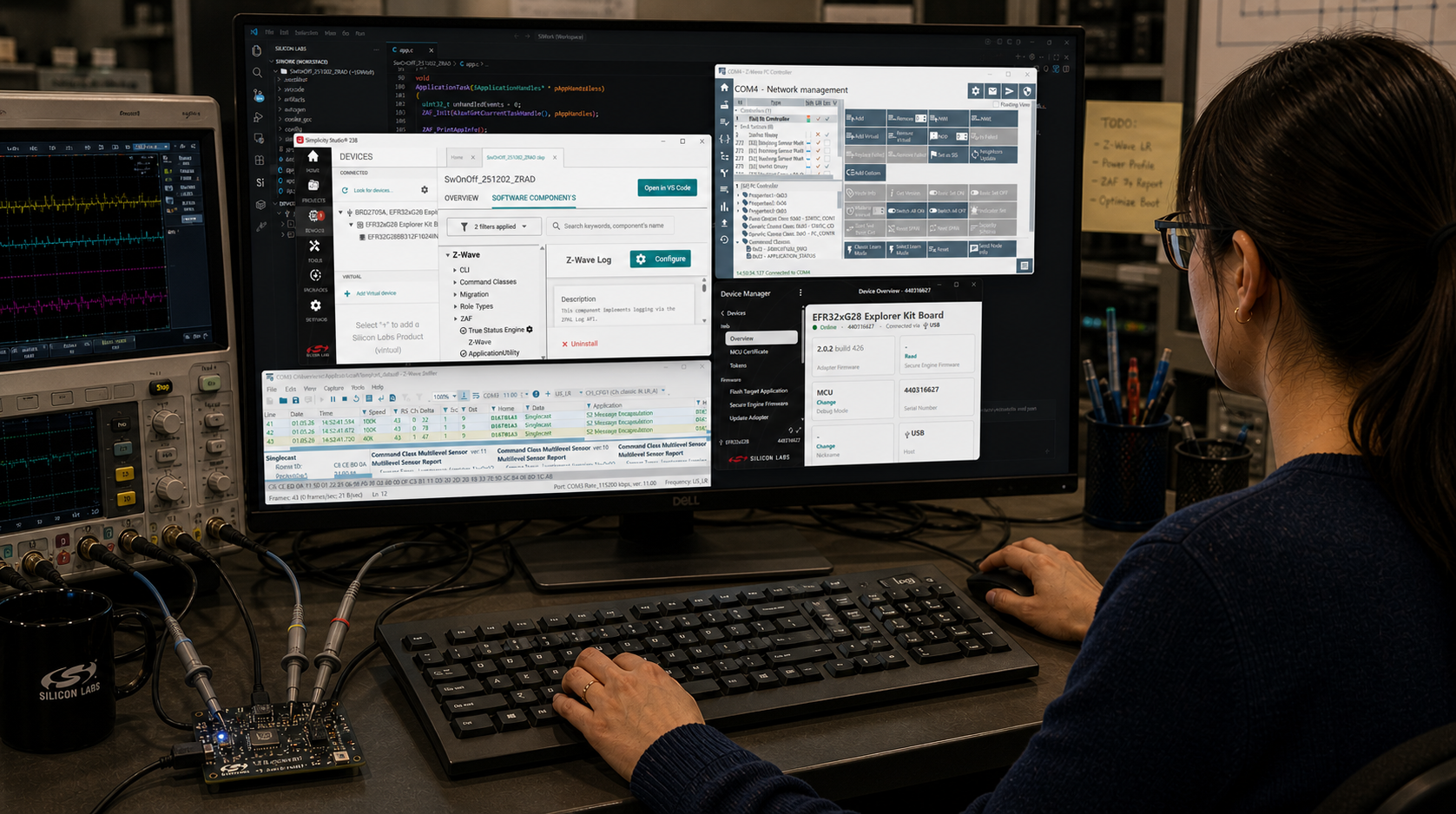
Open Simplicity Studio v5 (SSv5) which is the IDE for developing and debugging code for the EFR. I had already built a basic project starting with the Z-Wave SwitchOnOff sample app and was able to toggle an LED on my custom PCB. I had already created a bootloader, updated the SE, built and customized the sample app, joined a Z-Wave network and been in the debugger getting other parts of the project working. Now it was time to talk to the sensor so the first place to look is to click on the .SLCP file, then Software Components then search for “UART”. SSv5 then gives a long list of various drivers for various platforms, protocols, and applications. But all I want are the 4 functions listed above, why is this so complex already? There are no UART drivers for the Z-Wave protocol which is unfortunate as in the 500 series we did have the basic 4 functions prior to the move into SSv5. The first entry is Application->Utility->Simple Communication Interface (UART). The description talks about it being used for NCP communication but I’m not using NCP in this case so pass this one up. Next is Platform->Bootloader with four flavors of drivers but they are part of the bootloader and not the application so maybe not what I need? Next is Platform->Driver->UART which looks promising which I’ll discuss it in more detail shortly. Next is Services->Co-Processor Communication->secondary device->Driver which again has a single line description for a co-processor but no details of why I would use it so pass on this one too. Next is Third Party->Amazon FreeRTOS->Common I/O IoT UART which while I am using FreeRTOS I am not using the Amazon flavor. Looking at the link in the description there are similar functions to the 4 I want but with somewhat more OSish sounding names. Finally there are WiSun, Zigbee and Silicon Labs Matter drivers each with just 1 line descriptions and seem to be specific to the protocol. They also seem to be specific to Silicon Labs DevKit boards but I’m not using a DevKit, I have my own custom board so these don’t seem to be usable either. This is a case of information overload and simply sorting thru the options seems like a waste of time. Why are there so many flavors of this common API?
I had enabled DEBUGPRINT in the Z-Wave sample app so I was already aware of the IO Stream EUSART driver which is what the printf functions sprinkled thru the Z-Wave code use. With all of these options I spent about 1 hour reading just the section headings of the documentation looking for the simple function I need. Next step is to “install” a driver and try it out.
Step 4: UART Driver – IO Stream – 60 minutes
Since DEBUGPRINT uses the IO Stream driver, I assumed that would be the way to go for my use case as it should share most of the code already. I clicked on the + Add New Instances in SSv5, selected the desired baud rate, start/stop/parity and named the instance to differentiate it from the “vcom” instance used by the DEBUGPRINT utilities. The documentation is online and is versioned so I browsed thru that looking for my 4 functions. There is an Init routine and an IRQ handler but I was looking to avoid interrupts at least until I have have finished the trial-and-error of getting the sensor to send anything intelligible. I spent an hour trying to understand how this works without a PUTCHAR when I finally understood that only the “last stream initialized” “owns” the PRINTF functions. Since this driver uses DMA and interrupts it is way more complicated than I need and I don’t want to interfere with the DEBUGPRINT utilities. Uninstalled the IO Stream driver instance after wasting 60 minutes RTFMing and trying to follow the code.
Step 5: UART Driver – uartdrv – 6 hours
Going back to SSv5 and looking thru the options for UART Drivers I found Platform->Driver->UART->UARTDRV EUSART and installed it. SSv5 let me enter the board rate, parity, stop bits and several other options. I picked EUSART1 since it is able to drive all GPIOs and connected the proper GPIOs from my schematic. SSv5 installed a bunch of files mostly in the config folder and specifically the sl_uartdrv_eusart_mod_config.h which held the baud rate and various other UART settings. Next step is to look thru the documentation for my 4 simple functions. Unfortunately there are 27 functions and nothing obvious being the ones I need. But, I sallied forth and spent time reading the manual as well as looking thru the code and eventually was able to add enough code to my project to receive at least a few bytes. But the bytes I received don’t match the values the sensor should be sending. The other problem is that the UARTDRV_Receive function appears to wait for the buffer I gave it to fill up before returning. But I need to have each byte returned to me so I can decode which command is being sent and each one is a different size. These functions are way too complicated, the documentation is sparse and confusing and the API doesn’t have usable functions for my (or any?) application. I spent the better part of a day trying to get this “driver” to work but in the end it was taking me more time to figure out how to use it than if I just wrote my own.
Step 6: Peripheral – EUSART – 3 hours
I went back to SSv5 and searched for USART instead of UART and this time I found Platform->Peripheral->EUSART. This low level API is already installed I assume via the IO Stream for the DEBUGPINT utilities. The documentation lists 23 functions in the API but many of these are specific to the modes I’m not using like SPI or IrDA so I can simply ignore those. There is an Init function and EUSART_Rx and EUSART_Tx which are basically GetChar and PutChar. The API does not setup the clocks or the GPIOs but the examples explain how to do that. The documentation is clouded with all the many features like 9-bit data and SPI making it harder to decipher how to do basic UART operations.
Looking at the EUSART_UartInitHf function it becomes immediately obvious that this code is trying to be all things for all applications on all Silabs chips. The code both doesn’t do enough and does way too much at the same time! For example, the code writes all the registers back to their default value. Which is necessary if the UART is in an unknown state and is certainly the safe thing to do. However, this type of thing is rarely ever needed as the application will power up the chip, set the UART configuration once, and then never change it again. Maybe the baud rate will change but that function will write the necessary registers without needing everything to be set to the default. Not only is there a ton of code but there are several good size structures which are wasting both FLASH and RAM. Embedded systems are defined by the limited resources which include CPU time, FLASH and RAM. Drivers should be efficient and not waste these valuable resources. If an application needs to reset every register in the UART, then let the 0.001% of customers write their own! I gave up after spending another morning reading and trying stuff out and trying in vain to follow the code. Too complicated!
Step 7: Write My Own UART Driver – 2 hours
I spent less than two hours writing my own UART drivers. Why would I do that? Because it was easy and does exactly what I want with easy to understand code that anyone can follow. My driver is not universal and does not handle every option or error condition. But it does what 99% of applications need. The code is less than a few dozen bytes and uses only a few dozen bytes of RAM. The more lines of code, the more bugs and this code is so small you can check it by inspection.
Most of those two hours were spent reading documentation and trying to find where the interrupt vectors are “registered”. Turns out startup_efr32zg23.c in the SDK assigns all the vectors to a weak Default_Handler. All I had to do to “register” the ISR is give the function the proper name and the compiler plugs it into the vector table for me.
I did spend perhaps another couple of hours figuring out how to add an event to the ZAF_Event_Distributor, adding the event and some additional code to search for the proper sensor data in the byte stream. The key is in the ISR to use ZAF_EventHelperEventEnqueueFromISR to put an event into the FreeRTOS queue which is then processed in the zaf_event_distributor_app_event_manager function in SwitchOnOff.c.
Below is UART_DRZ.C which has the three functions needed and an interrupt service routine to grab the data out of the EUSART quickly and the let the application know there is data available.
/*
 * @file UART_DRZ.c
 * @brief UART Driver for Silicon Labs EFR32ZG23 and related series 2 chips
 *
 *  Created on: Jul 10, 2023
 *      Author: Eric Ryherd - DrZWave.blog
 *
 * Minimal drivers to initialize and setup the xG23 UARTs efficiently and provide simple functions for sending/receiving data.
 * Assumes using the EUSARTs and not the USART which has limited functionality and only a 2 byte buffer vs 16 in the EUSART.
 * Assumes high frequency mode (not operating in low-power modes with a low-frequency clock)
 * This example just implements a set of drivers for EUSART1. The code is tiny so make copies for the others as needed.
 */

#include <em_cmu.h>
#include <zaf_event_distributor_soc.h> // this is new under GSDK 4.4.1
#include "UART_DRZ.h"
#include "events.h"

// Rx Buffer and pointers for EUSART1. Make copies for other EUSARTs.
static uint8_t RxFIFO1[RX_FIFO_DEPTH];
static int RxFifoReadIndx1;
static int RxFifoWriteIndx1;
//static uint32_t EUSART1_Status;

/* UART_Init - basic initialization for the most common cases - works for all EUSARTs
 * Write to the appropriate UART registers to enable special modes after calling this function to enable fancy features.
 */
void UART_Init( EUSART_TypeDef *uart,   // EUSART1 - Pointer to one of the EUSARTs
    uint32_t baudrate,                  // 0=enable Autobaud, 1-1,000,000 bits/sec
    EUSART_Databits_TypeDef databits,   // eusartDataBits8=8 bits - must use the typedef!
    EUSART_Stopbits_TypeDef stopbits,   // eusartStopbits1=1 bit - follow the typdef for other settings
    EUSART_Parity_TypeDef parity,       // eusartNoParity
    GPIO_Port_TypeDef TxPort,           // gpioPortA thru D - Note that EUSART0 and 2 have GPIO port limitations
    unsigned int TxPin,
    GPIO_Port_TypeDef RxPort,
    unsigned int RxPin)
{

    // Check for valid uart and assign uartnum
    int uartnum = EUSART0 == uart ? 0 :
        EUSART1 == uart ? 1 :
        EUSART2 == uart ? 2 : -1;
    EFM_ASSERT(uartnum>=0);

    CMU_Clock_TypeDef clock = uartnum == 0 ? cmuClock_EUSART0 :
        uartnum == 1 ? cmuClock_EUSART1 : cmuClock_EUSART2;

    if (uartnum>=0) {
        // Configure the clocks
        if (0==uartnum){
            CMU_ClockSelectSet(clock, cmuSelect_EM01GRPCCLK); // EUSART0 requires special clock configuration
        } // EUSART 1 and 2 use EM01GRPCCLK and changing it will cause VCOM to use the wrong baud rate.
        CMU_ClockEnable(clock, true);

        // Configure Frame Format
        uart->FRAMECFG = ((uart->FRAMECFG & ~(_EUSART_FRAMECFG_DATABITS_MASK | _EUSART_FRAMECFG_STOPBITS_MASK | _EUSART_FRAMECFG_PARITY_MASK))
                | (uint32_t) (databits) // note that EUSART_xxxxxx_TypeDef puts these settings in the proper bit locations
                | (uint32_t) (parity)
                | (uint32_t) (stopbits));

        EUSART_Enable(uart, eusartEnable);

        if (baudrate == 0) {
            uart->CFG0 |= EUSART_CFG0_AUTOBAUDEN;       // autobaud is enabled with baudrate=0 - note that 0x55 has to be received for autobaud to work
        } else {
            EUSART_BaudrateSet(uart, 0, baudrate);    // checks various limits to ensure no overflow and handles oversampling
        }

        CMU_ClockEnable(cmuClock_GPIO, true);    // Typically already enabled but just to be sure enable the GPIO clock anyway

        // Configure TX and RX GPIOs
        GPIO_PinModeSet(TxPort, TxPin, gpioModePushPull, 1);
        GPIO_PinModeSet(RxPort, RxPin, gpioModeInputPull, 1);
        GPIO->EUSARTROUTE[uartnum].ROUTEEN = GPIO_EUSART_ROUTEEN_TXPEN;
        GPIO->EUSARTROUTE[uartnum].TXROUTE = (TxPort << _GPIO_EUSART_TXROUTE_PORT_SHIFT)
            | (TxPin << _GPIO_EUSART_TXROUTE_PIN_SHIFT);
        GPIO->EUSARTROUTE[uartnum].RXROUTE = (RxPort << _GPIO_EUSART_RXROUTE_PORT_SHIFT)
            | (RxPin << _GPIO_EUSART_RXROUTE_PIN_SHIFT);
    }

    RxFifoReadIndx1 = 0; // TODO - expand to other EUSARTs as needed
    RxFifoWriteIndx1 = 0;

    // Enable Rx Interrupts
    EUSART1->IEN_SET = EUSART_IEN_RXFL;
    NVIC_EnableIRQ(EUSART1_RX_IRQn);
}

/* EUSART1_RX_IRQHandler is the receive side interrupt handler for EUSART1.
 * startup_efr32zg23.c defines each of the IRQs as a WEAK function to Default_Handler which is then placed in the interrupt vector table.
 * By defining a function of the same name it overrides the WEAK function and places this one in the vector table.
 * Change this function name to match the EUSART you are using.
 *
 * This ISR pulls each byte out of the EUSART FIFO and places it into the software RxFIFO.
 */
void EUSART1_RX_IRQHandler(void){
  uint8_t dat;
  uint32_t flags = EUSART1->IF;
  EUSART1->IF_CLR = flags;                // clear all interrupt flags
  NVIC_ClearPendingIRQ(EUSART1_RX_IRQn);  // clear the NVIC Interrupt

  for (int i=0; (EUSART_STATUS_RXFL & EUSART1->STATUS) && (i<16); i++) { // Pull all bytes out of EUSART
      dat = EUSART1->RXDATA;                  // read 1 byte out of the hardware FIFO in the EUSART
      if (EUSART1_RxDepth()<RX_FIFO_DEPTH) { // is there room in the RxFifo?
          RxFIFO1[RxFifoWriteIndx1++] = dat;
          if (RxFifoWriteIndx1 >= RX_FIFO_DEPTH) {
              RxFifoWriteIndx1 = 0;
          }
      } else {  // No room in the RxFIFO, drop the data
          // TODO - report underflow
          break;
      }
      // TODO - add testing for error conditions here - like the FIFO is full... Set a bit and call an event
  }
  // TODO - check for error conditions
  zaf_event_distributor_enqueue_app_event(EVENT_EUSART1_CHARACTER_RECEIVED); // Tell the application there is data in RxFIFO
}

// Return a byte from the RxFIFO - be sure there is one available by calling RxDepth first
uint8_t EUSART1_GetChar(void) {
  uint8_t rtn;
  rtn = RxFIFO1[RxFifoReadIndx1++];
  if (RxFifoReadIndx1>=RX_FIFO_DEPTH) {
    RxFifoReadIndx1 = 0;
  }
  return(rtn);
}

// Put 1 character into the EUSART1 hardware Tx FIFO - returns True if FIFO is not full and False if FIFO is full and the byte was not added - nonblocking
bool EUSART1_PutChar(uint8_t dat) {
  bool rtn = false;
  if (EUSART1->STATUS & EUSART_STATUS_TXFL) {
      EUSART1->TXDATA = dat;
      rtn = true;
  }
  return(rtn);
}

// number of valid bytes in the RxFIFO - use this to avoid blocking GetChar
int EUSART1_RxDepth(void) {
  int rtn;
  rtn = RxFifoReadIndx1 - RxFifoWriteIndx1;
  if (rtn<0) {
      rtn +=RX_FIFO_DEPTH;
  }
  return(rtn);
}
The corresponding UART_DRZ.h file:
/*
 * UART_DRZ.h
 *
 *  Created on: Jul 10, 2023
 *      Author: eric
 */

#ifndef UART_DRZ_H_
#define UART_DRZ_H_

#include <em_eusart.h>
#include <em_gpio.h>

void UART_Init( EUSART_TypeDef *uart,        // Pointer to one of the EUSARTs
    uint32_t baudrate,                  // 0=enable Autobaud, 1-1,000,000 bits/sec
    EUSART_Databits_TypeDef databits,
    EUSART_Stopbits_TypeDef stopbits,
    EUSART_Parity_TypeDef parity,
    GPIO_Port_TypeDef TxPort,
    unsigned int TxPin,
    GPIO_Port_TypeDef RxPort,
    unsigned int RxPin);

int EUSART1_RxDepth(void);
uint8_t EUSART1_GetChar(void);

// Rx FIFO depth in bytes - make it long enough to hold the longest expected message
#define RX_FIFO_DEPTH 32

#endif /* UART_DRZ_H_ */
The code above was updated 3/28/2024 to match the GSDK 4.4.1 release. I plan to release this code under github soon so it can be easily incorporated into any project and kept more up-to-date.
Conclusions
For all the talk of “Modular Code”, “Code ReUse”, “APIs” and of course AI generated code, embedded systems are unique due to their limited resources. Limited resources means you cannot throw generic “modular” code at a problem if it bloats the resulting application. Embedded Engineers are also a limited resource and in short supply. Reusing tested, well written, well documented code is a huge time saver. However, if the problem is simple, it may be more efficient to write it yourself. Certainly that was the case in this scenario.
I’ve mentioned before that embedded engineers are usually at least 2 weeks (if not 2 months!) late in a project from the very first day. By the time marketing, finance and management decide on the product features, fund it, and allocate engineering resources, the project is already behind schedule. Chip vendors need to make the engineers job easier by providing APIs that serve 90% of the needs without obfuscating the calls under a ton of features few people will ever use. The API needs to be intuitive and not require hours of reading manuals or randomly trying stuff until they work. Hide the complexity and provide easy to use functions with concise but detailed documentation with a few examples (I love to cut and paste!).
On the hardware side, I have a rule of thumb that if a customer isn’t willing to pay an extra nickel per chip for a feature, then do not include it! The time it takes to spec, design, code, document, validate in simulation, validate the silicon, document again (due to invariable changes), write silicon test programs, run extra test vectors on every chip, and finally develop training, (WHEW!) far outweigh the brain-fart feature someone thought might be cool. When instancing multiple copies of a peripheral, they should all be the same. Then you can reuse all of the above whereas if they are different you have to make special versions of everything, especially the documentation. Users will first assume they are all the same. They will strongly dislike the fact that one EUSART can route to all GPIOs whereas the others have limitations. Why is there a USART in the xG23 family? Why are the EUSARTs each just a little different? Why are there so many options in the EUSART? Does anyone use all these features? Will EVERYONE pay an extra nickel for the chip for features they don’t need? Obviously there are some features that are required, some that are expected, but there are a bunch that could be dropped.