The death of the 8-bit CPU has been prognosticated for over a decade but these old tiny workhorses keep going and going and going. Z-Wave is currently based on the venerable Intel 8051 CPU but we’re about to get an upgrade to a 32-bit ARM CPU via the 700 series which is due out later this year. In this posting I’ll give a few tips on coding in C for the 8051 to typically improve speed of execution.
I’ve been writing code for 8-bit CPUs since the 1980s and I designed a few in the 1990s. I also designed a couple of 32-bit RISC CPUs in the 1990s and early 2000s. I often had to squeeze the code just a little harder to get an operation to happen just fast enough to meet a system requirement. This meant that I either had to code in assembly or often just coding C in a slightly different way would convince the compiler to generate the most optimal assembly code for me.
8-bit CPU Architecture
I could go thru a long discussion of the block diagram of the 8051 CPU but instead I’ll just cut to the chase – the 8051 is not at all “C friendly”. The 8051 was architected back in the bad ol’ days of assembly programming – especially for embedded systems where resources were in very short supply (think 1K ROM and 64 bytes of RAM). Thus the architecture has all sorts of funny things that a C compiler can’t take advantage of efficiently. The PSR flags, the D pointer, the single accumulator, memory mapped registers and the SFR registers are all parts of the 8051 that make it special but unfortunately are just not efficient in C. The folks at Keil have worked really hard to make their compiler as efficient as possible and to make access to these non-C hardware resources available without too much effort. But at the end of the day, a C compiler really wants a nice simple block of 32-bit registers to perform integer arithmetic on and a simple flat memory – in other words, a RISC CPU.
In the Z-Wave world, the 8051 in the 500 series chips is a 32 MHz 8051 with 128K bytes of FLASH and 16K bytes of RAM. “But wait” you say, “the 8051 is an 8-bit CPU with a 16-bit Program Counter, how can it address 128K bytes?”. The answer is Bank Switching which is just plain crazy but I won’t get onto that soapbox in this posting. The Z-Wave code from Silicon Labs is delivered as pre-compiled C libraries that the application developer links into their code. The application code is written in C and the Keil compiler does a fine job of squeezing a reasonable amount of code into the tiny 8051. Fortunately in IoT, the task to be performed is usually pretty simple – turn a light on or off by activating a relay connected to a GPIO so we don’t need a multi-Gigahertz CPU with gobs of RAM.
The Silicon Labs SDK comes with a number of sample applications and a bunch of “helper” routines all written in C. Thus, a Z-Wave application can generally be written completely in C, compiled using the Keil compiler and it’ll generally squeeze into the limited code space as long as you don’t try to do too much on this little CPU. But it seems there are always some little things that I just need to do a little faster. The following tips are just a few of the simple tricks I’ve learned from decades of embedded coding.
The Fastest 8051 Loop
What is the fastest 8051 loop you can execute in C?
The most common loop is a simple FOR loop:
for (iter=0;iter<16;iter++) {
...
}
Which is easy to read and does the job just fine – if we don’t need to do it very fast. Often the innermost loop is executed a lot and squeezing just a few instructions out of the code will significantly improve the performance of the routine.
The for loop above compiles into the following assembly code:
B02:0xA04D E4 CLR A
B02:0xA04E FF MOV R7,A
B02:0xA04F 0F INC R7                    ; TOP OF LOOP
B02:0xA050 EF MOV A,R7
B02:0xA051 B410FB CJNE A,#demodState(0x10),B02:A04F
Which as you can see is quite a few instructions and even longer when you consider that each instruction is at least 4 CPU clocks. The Compare and Jump if Not Equal (CJNE) is a 3 byte instruction which requires many clock cycles to execute. If we can squeeze a few instructions out of the loop then it will run much faster. Obviously we could code in assembly but this exercise is to show that HOW you code in C can make a big difference in the performance. An alternative coding of the for loop above is:
iter=16;
do {
...
} while (--iter);
With this slight change in the coding style the while loop turns into a single byte DJNZ opcode as shown below so this is the fastest and most efficient looping structure when targeting the 8051.
B02:0xA055 7F10 MOV R7,#demodState(0x10)
B02:0xA057 DFFE DJNZ R7,B02:A057         ; single instruction loop
The real trick to improving the performance of your code is to see what assembly instructions the code compiles into.
How to See What Your C Code Turns Into
You can’t improve the performance of your code unless you can measure what the performance is and where all the time is being spent. A classic method of measuring the performance is to set a GPIO pin high or low during specific routines. Then use an oscilloscope to observe how long the routine takes. Other options involve printing out markers out a UART or using a hardware timer to measure the duration of a routine.
 A simple method to observe the instructions our C code generates for our little 8051 CPU is to use the simulator built into the Keil C compiler. By default the Keil IDE does not have a simulator when using the Silicon Labs sample projects so you have to assign one. Right click on the project then select “options” then click on the “Debug” tab. Then enter “s8051” into the CPU DLL box as shown here. You can now click on Debug->Start/Stop Debug Session or press <CTL>F5. This will enter the Keil Simulator for the 8051. One thing to understand is that this simulator does NOT understand the bank switching of the Silicon Labs version of the 8051 used in the 500 series. Unfortunately you can’t debug code much using this simulator as any bank switching doesn’t work. But it will work well enough to debug small snippets of code and of course to see what you code turns into.
 Once the debugger opens in the IDE, click on the line of code you are interested in and the Disassembly window (use View->Disassembly if its not visible) will take you right to the line of code you are interested in as shown here. Note that the C source code is mixed in as comments in the assembly code. This helps guide you to match the C code to the assembly code which can be a little convoluted depending on the optimization the compiler has applied. You can see here that the Do-While has turned into our desired DJNZ single instruction loop.
Don’t rely strictly on the instruction count to guide your C coding style. One slow-down I often see in the Silicon Labs code is they call a subroutine, that calls a subroutine, that calls (several more) subroutines which finally just returns a value. While this may be structured C coding it is very slow in an 8051. Each subroutine call pushes and pops a number of registers and parameters on the stack and each of those takes several clock cycles to perform. Ideally a C macro is used to specify a value or a register which becomes just a single instruction fetch of the value from a register or memory instead of all this pushing and popping.
Unrolling Loops
Another easy speedup in C is to unroll short loops. A classic situation for unrolling loops is when emulating a serial protocol like I2C with a GPIO. Since the loop is typically only 8 passes you can often significantly improve performance by unrolling the loop – often taking the I2C bit rate from under 10Kbps to nearly 100Kbps.
for (bitnum=0x80; bitnum!=0;bitnum>>1) {
    I2C_SEND_BIT(data & bitnum);  // macro to set SDA then toggle SCL
}
When unrolled turns into:
    I2C_SEND_BIT(data & 0x80);
    I2C_SEND_BIT(data & 0x40);
    I2C_SEND_BIT(data & 0x20);
    I2C_SEND_BIT(data & 0x10);
    I2C_SEND_BIT(data & 0x08);
    I2C_SEND_BIT(data & 0x04);
    I2C_SEND_BIT(data & 0x02);
    I2C_SEND_BIT(data & 0x01);
Which works well for short fixed length loops but obviously won’t work in every case. The slow down with the FOR loop involves reloading the accumulator and the D pointer with various constants and the iteration value. The inline version doesn’t have any of these nor are there any delays from looping. This technique also works well on 32-bit RISC processors.
Conclusion
There are a lot more tricks when coding for small 8-bit CPUs. But I’m hoping I won’t have to bother with them for much longer and the dominance of the 32-bit CPU will finally crush the 8-bit out of existence. The price of silicon continues to drop and 32-bit CPUs are often as cheap or even cheaper than these ancient 8-bit boat anchors. The modern CPUs also come with advanced debuggers unlike the 8051 which has… wait for it… printf or worse yet simply toggling an IO. Ugh.


 The Z-Wave team in Copenhagen resides in this modest building. Danes love to bicycle to work or take the excellent train/bus system. Only a few travel via car unlike those of us in the US who just love sitting in traffic for hours. The food in Copenhagen is wonderful with plenty of international choices as well as the Danish favorites. My hotel room is more of a spaceship pod than a boring room with the Danish penchant for efficient minimalism. The view of the windmills in the distance and the quaint classic European architecture are beautiful.
 Virtually all embedded systems must run 24 x 7 x 365 x many many years without ever being rebooted. Since there is no one there to “press the reset button” if the device fails, the watchdog timer is there to do just that. The 500 series Z-Wave chips from Silicon Labs have a watchdog timer and the example code provides a very minimal use of the watchdog timer. However, the minimal use in the example code is not sufficient to provide a robust watchdog for embedded Z-Wave devices. This post explains some rules and methods to code a robust watchdog timer.
 This diagram shows the Watchdog timers value which is constantly counting up. Every time the Watchdog is “kicked”, the counter is reset to zero. Somewhere in your code the ZW_WatchDogKick() routine is called which resets the watchdog timer. Sometimes this reset condition happens on a nice regular basis, sometimes it happens at varying times as shown by the level of the timer. The key is the timeout threshold has to be longer than any normal operating condition. If a fault condition occurs, the timer keeps on counting up until the threshold is reached and then the system is reset. When the watchdog timer fires, the Z-Wave chip goes thru a full reset just as if power had been removed and reapplied. Your embedded system is back up and running as if nothing had happened.
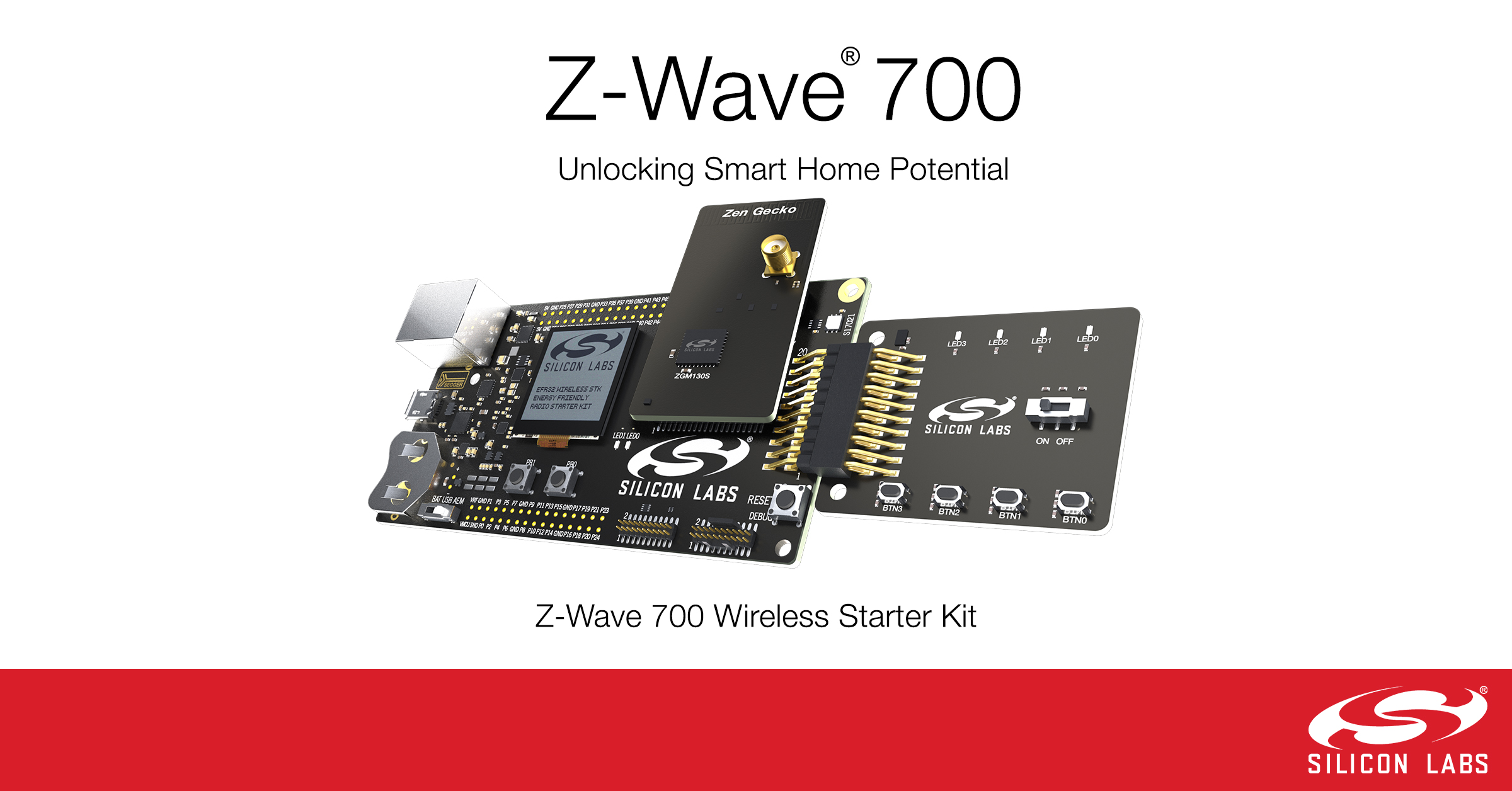
 I gave a presentation on Configuration Command Class Version 4 and all the wonderful things it can do. The most notable point is that 2/3rds of the Z-Wave Plus certified devices have at least one Configuration Parameter. Yet many hubs have no way of modifying or displaying to the user the current value of parameters. Z-Wave Plus V2 mandates support for Configuration Command Class V4 for both hubs and devices so you need to get busy! My presentation title is: “The Chicken vs Egg is over: Moving Your Product to Configuration Version 4” which can be downloaded from this link:
 IoT Device Testing Best Practices by Eric Ryherd
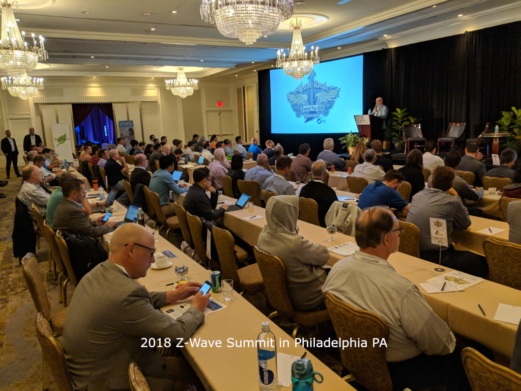
 There were nearly 200 attendees at the Summit – a significant increase over last year. One of the main purposes of the summit is to learn what’s new in Z-Wave and what Silicon Labs is planning for the future. The most important news at this year’s summit is the 700 series which was
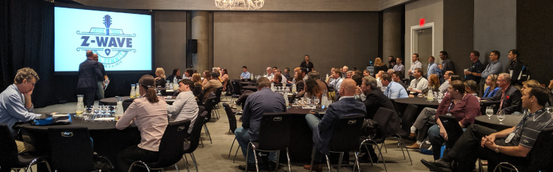
  The Summit isn’t all work all day even though the days are long and filled with lots of technical information. This summit had an evening at the